
Bicycle hub and bicycle wheel

a technology for bicycles and hubs, applied in the field of bicycle hubs, can solve the problems of increasing so as to reduce the cost of manufacturing, the effect of reducing the rigidity of the wheel

Inactive Publication Date: 2014-06-26
SHIMANO INC
View PDF9 Cites 11 Cited by
  • Summary
  • Abstract
  • Description
  • Claims
  • Application Information

AI Technical Summary

Benefits of technology

The patent text discusses the issues with traditional bicycle wheels that use expensive and complicated hubs with special attachment structures. These structures can reduce the rigidity of the wheel and make it difficult and expensive to replace spokes. The patent aims to provide a solution with a simpler structure that effectively arranges a plurality of spokes. The technical effect of this invention is to provide a more cost-effective and efficient bicycle hub that improves the arrangement of spokes and increases the overall rigidity of the wheel.

Problems solved by technology

It has been discovered that some of the hubs that are used with straight spokes can be expensive and / or complicated to manufacture due to the special attachment structures for securing the inner end to the hub shell or body.
Moreover, it has also been discovered that these types of wheels are not always as lightweight, as desired, due to these special attachment structures.
Furthermore, it has been discovered that with these types of bicycle wheels, it can be difficult, complicated and / or expensive to replace a spoke or spokes.

Method used


Image

  • Bicycle hub and bicycle wheel
  • Bicycle hub and bicycle wheel
  • Bicycle hub and bicycle wheel

Examples


second embodiment

[0044]Referring now to FIG. 8, a center hub 112 (e.g., a bicycle hub) in accordance with a second embodiment will now be explained. The hub 112 is used with the rim 14 (e.g., an annular rim) and the spokes 16 to form the bicycle wheel 10 (e.g., a bicycle wheel) (see FIG. 1). In view of the similarity between the first and second embodiments, the parts of the second embodiment that are identical to the parts of the first embodiment will be given the same reference numerals as the parts of the first embodiment. Also, parts of this second embodiment that are functionally identical and / or substantially identical to parts of the first embodiment will be given the same reference numerals but with “100” added thereto. In any event, the descriptions of the parts of the second embodiment that are substantially identical to the parts of the first embodiment may be omitted for the sake of brevity. However, it will be apparent to those skilled in the art from this disclosure that the descriptio...

third embodiment

[0049]Referring now to FIG. 9, a center hub 212 (e.g., a bicycle hub) in accordance with a third embodiment will now be explained. The hub 212 is used with the rim 14 (e.g., an annular rim) and the spokes 16 to form the bicycle wheel 10 (e.g., a bicycle wheel) (see FIG. 1). In view of the similarity between the first and third embodiments, the parts of the third embodiment that are identical to the parts of the first embodiment will be given the same reference numerals as the parts of the first embodiment. Also, parts of this third embodiment that are functionally identical and / or substantially identical to parts of the first embodiment will be given the same reference numerals but with “200” added thereto. In any event, the descriptions of the parts of the third embodiment that are substantially identical to the parts of the first embodiment may be omitted for the sake of brevity. However, it will be apparent to those skilled in the art from this disclosure that the descriptions an...


PUM


Abstract

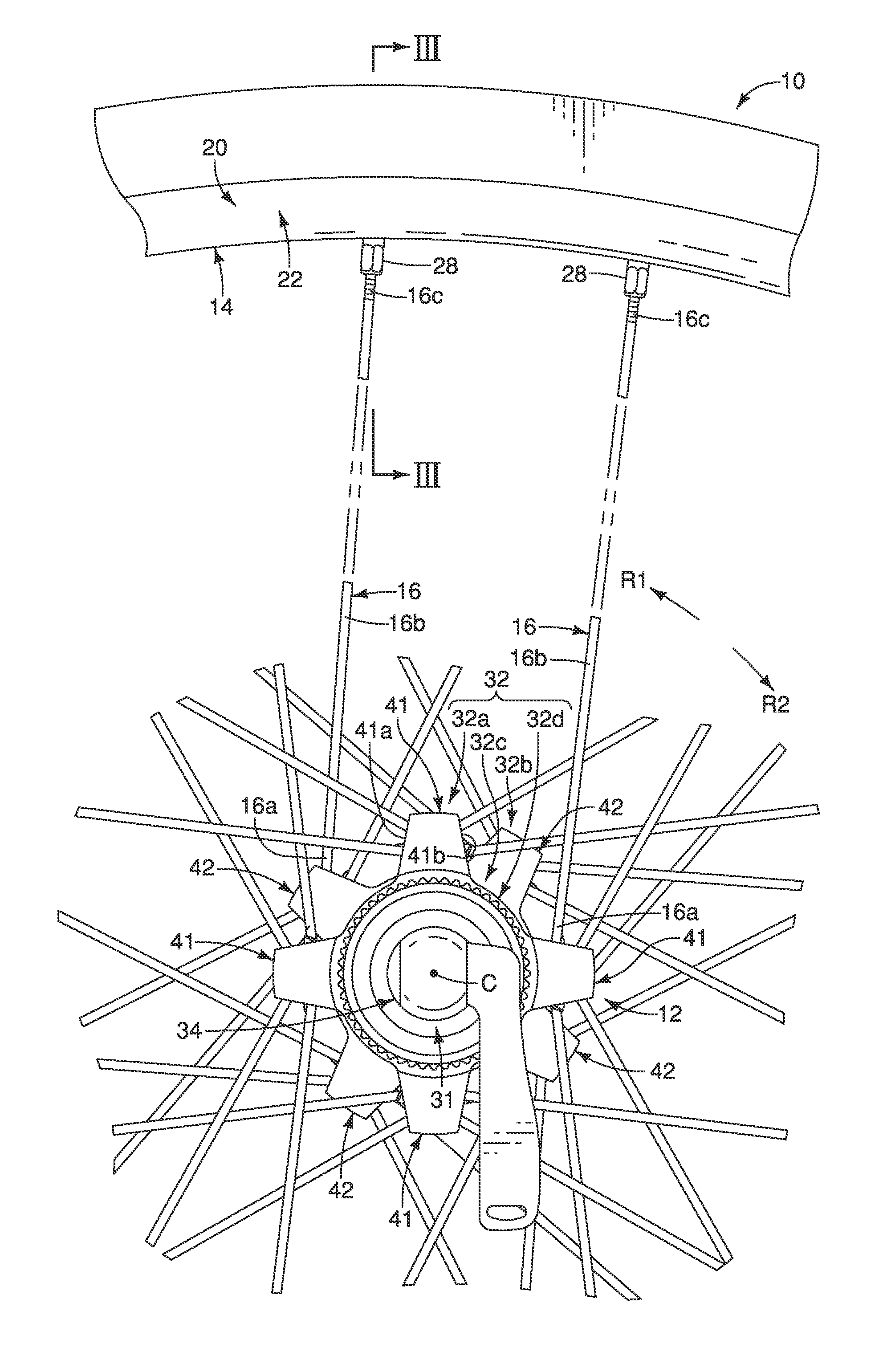
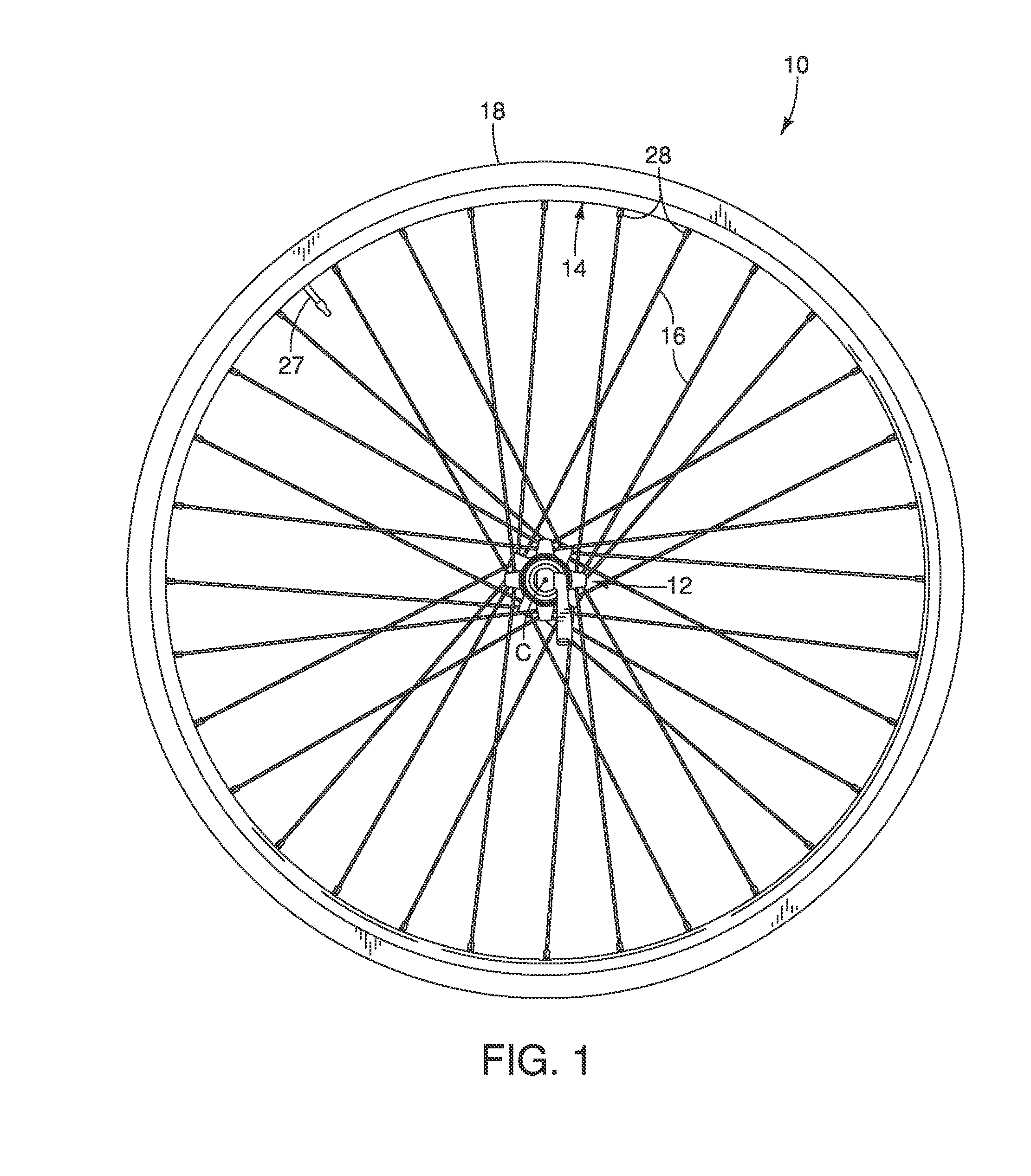
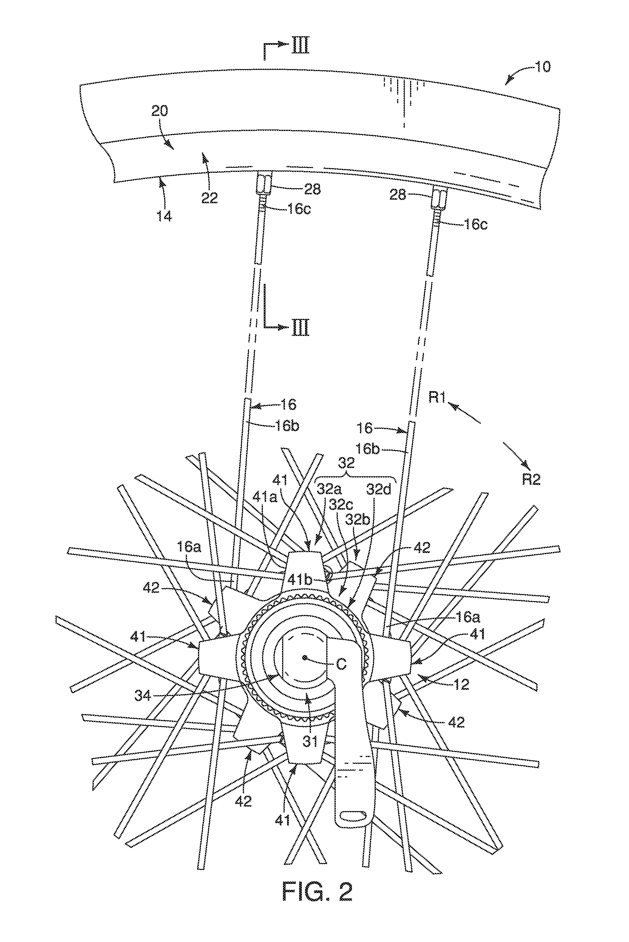
A bicycle hub includes a hub shell body and a plurality of spoke mounting projections. The spoke mounting projections are disposed at one end portion of the hub shell body. Each of the spoke mounting projections includes a first circumferential side and a second circumferential side. The first circumferential side has a first spoke outlet for a first spoke and a second spoke outlet for a second spoke. The second circumferential side is opposite to the first circumferential side.

Description

BACKGROUND[0001]1. Field of the Invention[0002]This invention generally relates to a bicycle hub. More specifically, the present invention relates to a bicycle hub with a plurality of spoke mounting projections.[0003]2. Background Information[0004]There are many different types of bicycle wheels, which are currently available on the market. Most bicycle wheels have a hub, a plurality of spokes and an annular rim. The hub is attached to a part of the frame of the bicycle for relative rotation. The inner ends of the spokes are coupled to the hub and extend outwardly from the hub. The annular rim is coupled to the outer ends of the spokes and has an outer portion for supporting a pneumatic tire thereon. Typically, the spokes of the bicycle wheel are thin metal wire spokes. The outer ends of the spokes typically are provided with threads for engaging spoke nipples, which secure the outer ends of the wire spokes to holes in the annular rim. Recently, bicycle wheels have been designed tha...

Claims


Application Information

Patent Timeline
Patent Type & Authority Applications(United States)
IPC IPC(8): B60B1/04B60B1/00
CPCB60B1/003B60B1/0261B60B1/041B60B1/042B60B1/043B60B27/023B60B27/026
Inventor KOSHIYAMA, KAZUKI
Owner SHIMANO INC
Learn More