Assembly for Extendable Rail-Supported Vehicle Coupler

Active Publication Date: 2014-09-18
BRANDT ROAD RAIL CORP
View PDF3 Cites 6 Cited by
  • Summary
  • Abstract
  • Description
  • Claims
  • Application Information

AI Technical Summary

Benefits of technology

The patent describes a brake pipe mounting bracket for a vehicle that is designed to allow the brake pipe to be rotated. This bracket can be used to either mount the brake pipe on the inside of the vehicle's exterior surface or on the outside of the bumper. It makes it easy to retract the brake pipe when needed and ensures that it is secure both in position. This bracket can be adjusted to secure the brake pipe in two different positions.

Problems solved by technology

While it is common to see such couplers projecting forwardly and / or rearwardly of railway cars, it has been found that there are situations where such projection is undesirable.
For example, in the case of so-called road / rail vehicles which can be driven on either rails or flat road surfaces due to the presence of both rail wheels and rubber tires, the projection of an unused coupler may result in a total vehicle length that exceeds highway use regulations.

Method used


Image

  • Assembly for Extendable Rail-Supported Vehicle Coupler
  • Assembly for Extendable Rail-Supported Vehicle Coupler
  • Assembly for Extendable Rail-Supported Vehicle Coupler

Examples


Embodiment Construction

[0030]In the following description, specific materials and dimensions are not addressed as such may vary by situation and will be determined at least in part by regulations, all of which would be known to those skilled in the art. In addition, the means for attaching the assembly to a particular rail-supportable vehicle will depend in part on the vehicle support structure and will accordingly not be canvassed herein.

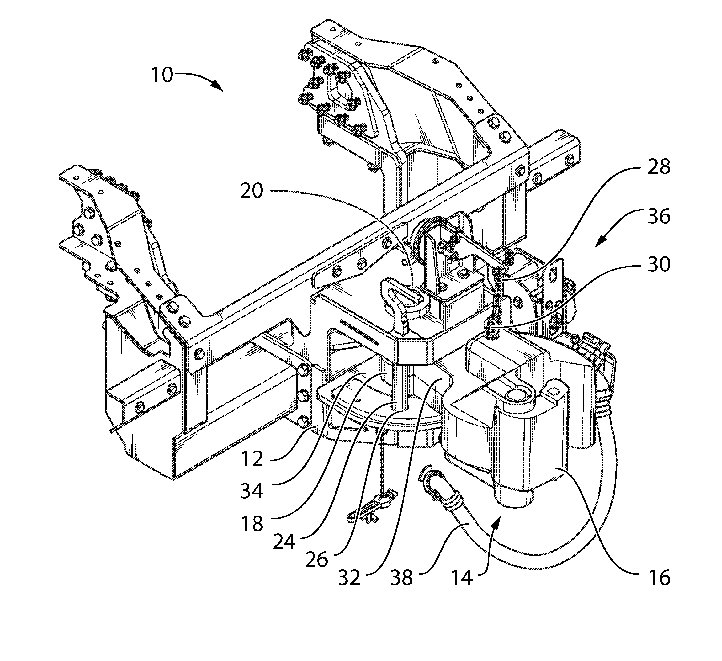
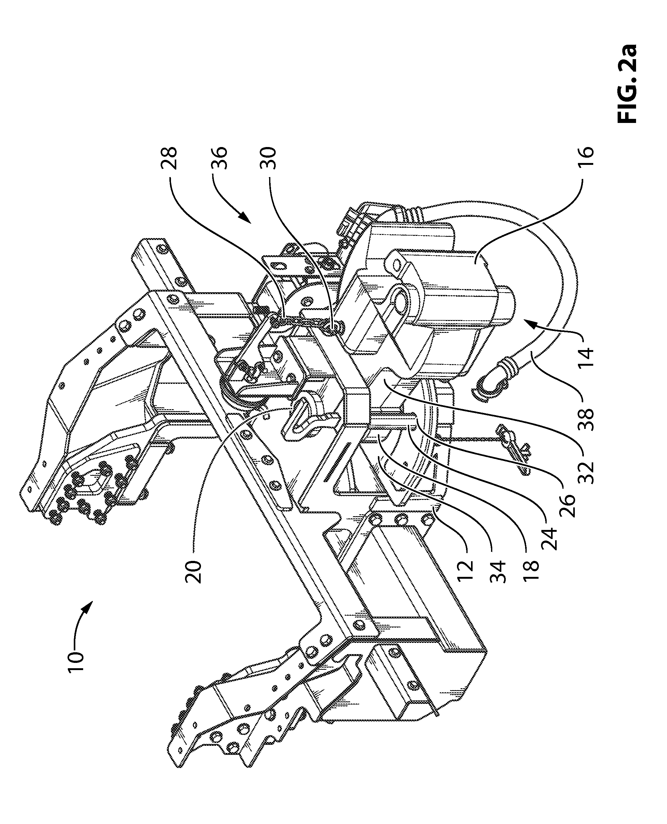
[0031]Turning to FIGS. 2a through 2f, an exemplary coupler assembly is illustrated and identified by reference numeral 10. The assembly 10 comprises a frame 12 which is configured for attachment to the internal structure of a rail-supported vehicle (not shown) in a manner which will be situation-specific but within the knowledge of those skilled in the art. The assembly 10 also includes a coupler 14, which coupler 14 comprises a shank 32 with a first end 16 provided with a standard coupling interface (which in the illustrated example is an AAR coupler) and a second end 1...


PUM


Abstract

A railcar coupler assembly allowing rotation of a coupler between a stored position within the railcar and an extended position for engagement with the coupler of an adjacent railcar. The coupler can be locked into either the stored or extended position with a locking pin. A corresponding rotatable brake pipe is also disclosed.

Description

FIELD[0001]The present disclosure relates to coupling assemblies for rail-supported vehicles such as railcars and road / rail vehicles.BACKGROUND[0002]It is known in the art of rail-supported vehicles or rolling stock to connect multiple units into a single train to enable transportation of increased amounts of materials or passengers. This connection is achieved by means of a coupling mechanism between cars, and numerous coupling mechanisms have been developed and standardized over the years. One example of such a coupling mechanism is the Janney coupler or knuckle coupler, which was subject of U.S. Pat. No. 138,405 and is in wide usage under specifications overseen by the Association of American Railroads, or AAR. An example of a prior art coupler is shown in FIG. 1a, the coupler 1 comprising a head 2 and pivot end 4 connected by a shank 3. Railcars are provided with both a coupler and a brake pipe, and both are connected to the coupler and brake pipe of an adjacent railcar to achie...

Claims


Application Information

Patent Timeline
IPC IPC(8): B61G7/10
CPCB61G7/10B61G7/08
Inventor BRODIE, DAVID
Owner BRANDT ROAD RAIL CORP
Why Eureka
Try Eureka