Integrated bipod tension stabilization rifle sling

Active Publication Date: 2014-10-02
NEVILS JACQUES A +1
View PDF20 Cites 3 Cited by
  • Summary
  • Abstract
  • Description
  • Claims
  • Application Information

AI Technical Summary

Benefits of technology

The present invention provides a novel rifle sling that can be easily and efficiently adjusted by a rifle user for application of a desired pulling or urging force of the buttstock against the shoulder of the user to enhance the stability and steadiness of the rifle during aiming and shooting. The sling is designed for engagement with each of the legs of a bipod for additional stability of the rifle during use particularly in the prone or other bipod stabilized aiming and shooting position. The sling mechanism is adjustable to provide a traction force that develops enhanced leverage to the rearward pressure of the firearm against the shoulder of the user for both stabilization for firing and recoil force management. The sling is easily adjusted to apply a tension force to the firearm to urge the firearm rearwardly, toward the user, so that the buttstock of the firearm is forced against a shoulder of the user with sufficient tightness that the efficiency and accuracy of aiming and shooting are enhanced. The sling mechanism is efficient in managing recoil force, allowing the user to make only minor adjustment of the position of the firearm following the firing of each ammunition round. The sling is designed to enhance the stability and accuracy of aiming and shooting, especially in long range firearm shooting matches.

Problems solved by technology

However, these types of slings are difficult to use and they typically permit a small degree of rifle movement during aiming and firing, and thus permit a certain degree of inaccuracy from the standpoint of bullet strike consistency.
Most of the adjustable slings of the prior art do not function to draw or urge the buttstock of a rifle tightly against the shoulder of the user, thus requiring the user to apply a manual pulling force to the rifle structure to hold the rifle tightly against the shoulder during aiming and shooting.
The muscle energy that is used for pulling and stabilizing the rifle during aiming typically interferes somewhat with the delicate digital force that is typically used for carefully pulling the trigger of the rifle in sequence with maintaining the aiming point with respect to the target.

Method used


Image

  • Integrated bipod tension stabilization rifle sling
  • Integrated bipod tension stabilization rifle sling
  • Integrated bipod tension stabilization rifle sling

Examples


Embodiment Construction

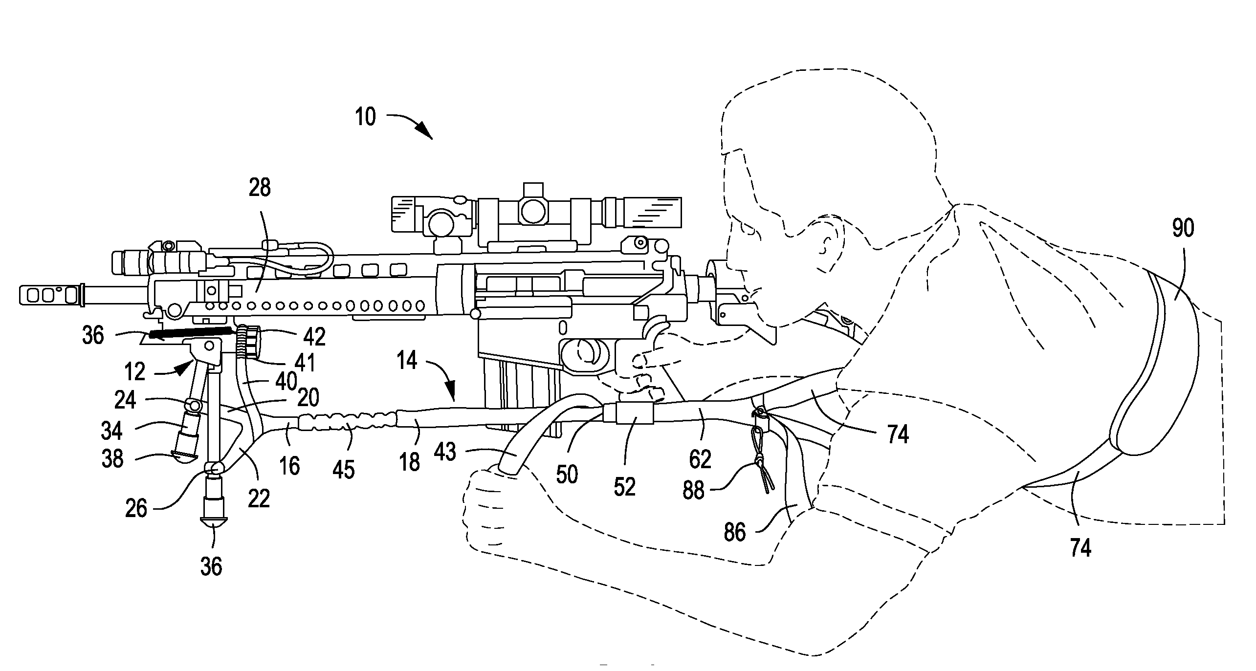
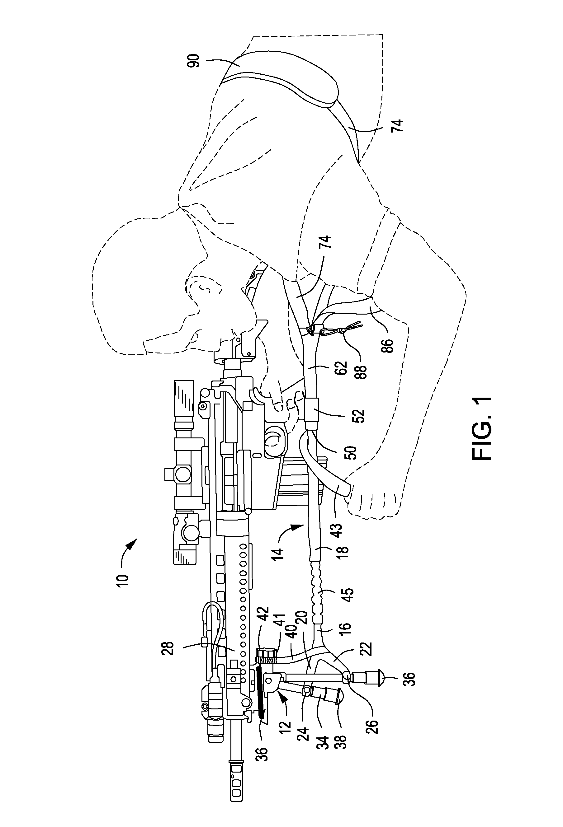
[0025]Referring now to the drawings and first to FIG. 1, a marksman, illustrated in broken lines, is shown in the prone aiming and shooting position, using a firearm, shown generally at 10, to which a bipod mechanism, shown generally at 12, is mounted. An integrated tension stabilization firearm sling, shown generally at 14, which embodies the principles of the present invention and represents the preferred embodiment, is shown in FIG. 1 to have tension applying connection both with the bipod mechanism 12 of the firearm, and with the body of the marksman, thereby providing the user with tension stabilized firearm positioning. The integrated tension stabilization firearm sling 14 has a firearm connector section, shown generally at 16, which is generally composed of flexible strap material. The firearm connector section 16 has a firearm or bipod attachment strap 18, which is preferably composed of a durable fabric material, such as the polymer material, Nylon, as are other strap compo...


PUM


Abstract

A firearm sling apparatus has a firearm connection section for attachment to a forward portion of a firearm and having a body connection section for attachment to the body of a firearm user. A releasable latching connector establishes releasable connection of the firearm connection section and the body connection section and provides for selective adjustment of strap members of the sling, permitting a user to adjust the body connection of the sling to fit the user's body anatomy and to accommodate the aiming and shooting position of the firearm. Adjustment of the sling apparatus is preferably accomplished with the user in a bipod stabilized position.

Description

BACKGROUND OF THE INVENTION[0001]1. Field of the Invention[0002]The present invention relates generally to shoulder fired firearms, such as rifles, shotguns and various types of tactical weapons. More particularly, the present invention concerns an adjustable sling device for a class of firearms typically referred to as “long guns” or “shoulder fired weapons” that enables shoulder fired weapons to be held tightly against the shoulder of the user during aiming and firing and causing the firearm to be returned substantially to its aiming position after the recoil impact of the firearm against the shoulder of the user has dissipated. Even more specifically, the present invention concerns a sling for long guns having a bipod mounted to the front portion thereof, the sling having a facility for attachment to the bipod and being easily adjustable for developing a traction force to urge the buttstock of the firearm against the shoulder of the user for aiming and firing of the firearm.[0003...

Claims


Application Information

Patent Timeline
IPC IPC(8): F41C33/00
CPCF41C33/001Y10S224/913
Inventor NEVILS, JACQUES A.GIANNELLI, CHANCE J.
Owner NEVILS JACQUES A
Why Eureka
Try Eureka