Infusion sleeve with distendable port

a technology of infusion sleeve and port, which is applied in the field of surgical instruments and surgical techniques, can solve the problems of reducing the flow of irrigating liquid into the eye, affecting the effect of fluid flow resistance, and easy damage to endothelial cells, so as to achieve the effect of reducing the resistance of fluid flow

Active Publication Date: 2014-10-16
ART LTD
View PDF5 Cites 0 Cited by
  • Summary
  • Abstract
  • Description
  • Claims
  • Application Information

AI Technical Summary

Benefits of technology

[0033]In one form, the invention is directed to a phacoemulsification irrigation sleeve having a body configured to operatively connect to a phacoemulsification needle. The body has proximal and distal ends and defines a passageway for liquid. A first irrigation port is provided on the body between the proximal and distal ends of the body through which fluid in the passageway can flow. The body is slit to define a first flap. The first flap is configured to swing away from the first irrigation port in response to pressure of fluid flowing in the passageway, to thereby reduce resistance of fluid flow through the first irrigation port. The first flap is configured so that the first flap, when swinging away from the first irrigation port, is oriented to direct fluid flowing through the first irrigation port in a direction from the proximal end of the body toward the distal end of the body.

Problems solved by technology

As an example, endothelial cells can easily be damaged during such a collapse and this damage is permanent because these cells do not regenerate.
If the sleeve is of the type having an infusion port at its tip, surrounding the needle, it may also become occluded.
When this happens, flow of irrigating liquid into the eye may decrease, meaning that not enough liquid flow may be available to help clear the occlusion.
If the surgeon acts to increase liquid flow through the infusion sleeve, this can cause an increase in the Reynolds number of the infusion liquid to the point where the liquid flow becomes turbulent, which can in itself cause damage to the eye.
The external baffles effectively increase the diameter of the sleeve while the internal baffles are relatively difficult or expensive to manufacture as compared to an extruded sleeve.

Method used


Image

  • Infusion sleeve with distendable port
  • Infusion sleeve with distendable port
  • Infusion sleeve with distendable port

Examples


Embodiment Construction

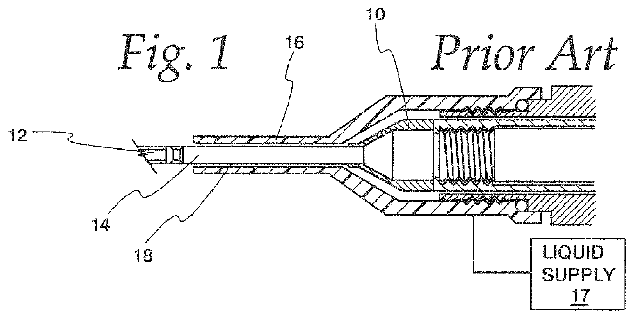
[0066]Referring now to FIG. 1, the numeral 10 indicates generally a partial sectional view of a prior art phacoemulsification hand piece having a needle 12 defining a hollow internal chamber 14 through which irrigation liquid and emulsified particles of a lens are aspirated from the capsular bag. As seen in FIG. 1, an irrigating sleeve 16 is mounted to hand piece 10, from which needle 12 protrudes. Sleeve 16 communications with an irrigation liquid supply 17 within handpiece 10 and provides irrigating liquid to the capsular bag through an annular channel 18 formed between needle 12 and sleeve 16.

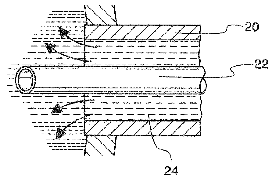
[0067]Referring now to FIG. 2, an enlarged partial sectional view of a second prior art phacoemulsification apparatus is shown having a sleeve 20 surrounding a hollow needle 22 and defining therebetween an annular channel 24 as a conduit for irrigating liquid.

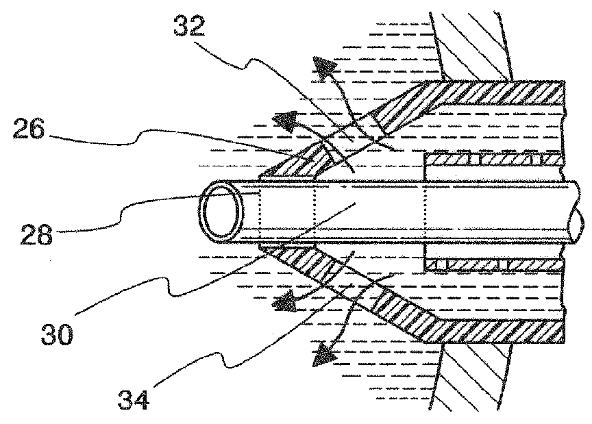
[0068]Both FIG. 1 and FIG. 2 show a prior art apparatus with the flow of irrigating liquid directed annularly about the periphery of t...


PUM


Abstract

A phacoemulsification irrigation sleeve having a body configured to operatively connect to a phacoemulsification needle. The body has proximal and distal ends and defines a passageway for liquid. A first irrigation port is formed in the body between its proximal and distal ends. The body is slit to define a first flap configured to swing away from the first irrigation port in response to pressure of fluid flowing in the passageway to thereby reduce resistance of fluid flow through the first irrigation port. The first flap, when swung away from the first irrigation port, is oriented to direct fluid flowing through the first irrigation port in a direction from the proximal end of the body toward the distal end of the body.

Description

CROSS-REFERENCE TO RELATED APPLICATIONS[0001]This application is a continuation-in-part of U.S. patent application Ser. No. 12 / 856,358, filed Aug. 13, 2010.BACKGROUND OF THE INVENTION[0002]1. Field of the Invention[0003]This invention relates to surgical instruments and surgical techniques used in eye surgery and, more particularly, to the technique of phacoemulsification apparatus and methods for their use.[0004]2. Background Art[0005]A common ophthalmological surgical technique is the removal of a diseased or injured lens from the eye. Earlier techniques used for the removal of the lens typically required a substantial incision to be made in the capsular bag in which the lens is encased. Such incisions were often on the order of 12 mm in length.[0006]Later techniques focused on removing diseased lenses and inserting replacement artificial lenses through as small an incision as possible. For example, it is now a common technique to take an artificial intraocular lens (IOL), fold it...

Claims


Application Information

Patent Timeline
Patent Type & Authority Applications(United States)
IPC IPC(8): A61M3/02A61M1/00A61F9/007
CPCA61M3/0279A61M1/0084A61F9/00745A61B2017/320084A61M1/85
Inventor AKAHOSHI, TAKAYUKI
Owner ART LTD
Why Eureka
Try Eureka