
Cooling apparatus for plated steel sheet

a cooling apparatus and plated steel technology, applied in hot-dipping/immersion processes, metal material coating processes, coatings, etc., can solve the problems of reducing productivity, and increasing the plating rate, so as to reduce the vibration of the steel sheet, improve the cooling performance, and reduce the effect of fluid flow resistan

Active Publication Date: 2019-03-19
POHANG IRON & STEEL CO LTD
View PDF24 Cites 0 Cited by
  • Summary
  • Abstract
  • Description
  • Claims
  • Application Information

AI Technical Summary

Benefits of technology

[0027]According to a plated steel sheet cooling apparatus of an exemplary embodiment in the present disclosure, a spraying width varying unit of an exemplary embodiment in the present disclosure varies a spraying width of a cooling fluid to correspond to a width of a steel sheet to improve a cooling performance and to reduce vibrations of the steel sheet. Furthermore, the spraying width varying unit is installed outside of a spraying unit so as not to interfere with a cooling fluid flow path inside of the spraying unit, and thus collisions of flows of a cooling fluid are prevented inside the spraying unit. Thus, fluid flow resistance is significantly reduced, and a reduction in a spraying pressure of the cooling fluid is prevented, thereby further increasing a cooling performance.
[0028]In addition, a spraying distance adjusting unit of an exemplary embodiment in the present disclosure adjusts a distance between the steel sheet and the spraying unit in consideration of a defect generation distance of a plating layer according to a solidified state of the plating layer to increase a cooling performance.

Problems solved by technology

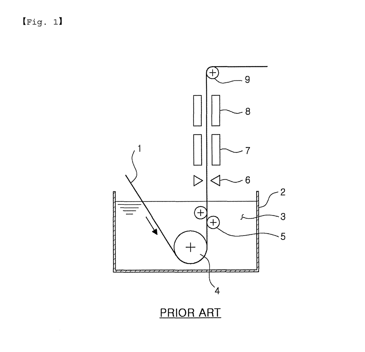
Such an increase in the vibrations of the steel sheet 1 may cause various problems in a plating line.
In addition, as it may be difficult to increase a plating rate of the steel sheet 1 due to the vibrations of the steel sheet, productivity may be reduced.
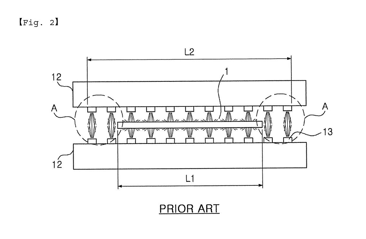
In addition, as illustrated in FIG. 2, in a case in which a narrow plated steel sheet is produced, an excessive amount of cooling fluids is sprayed even to areas in which the steel sheet 1 is not present in a width direction.
Thus, an air blower may be overloaded and a cooling efficiency thereof may be reduced, which may be various causes of a reduction in productivity.

Method used


Image

  • Cooling apparatus for plated steel sheet
  • Cooling apparatus for plated steel sheet
  • Cooling apparatus for plated steel sheet

Examples


Embodiment Construction

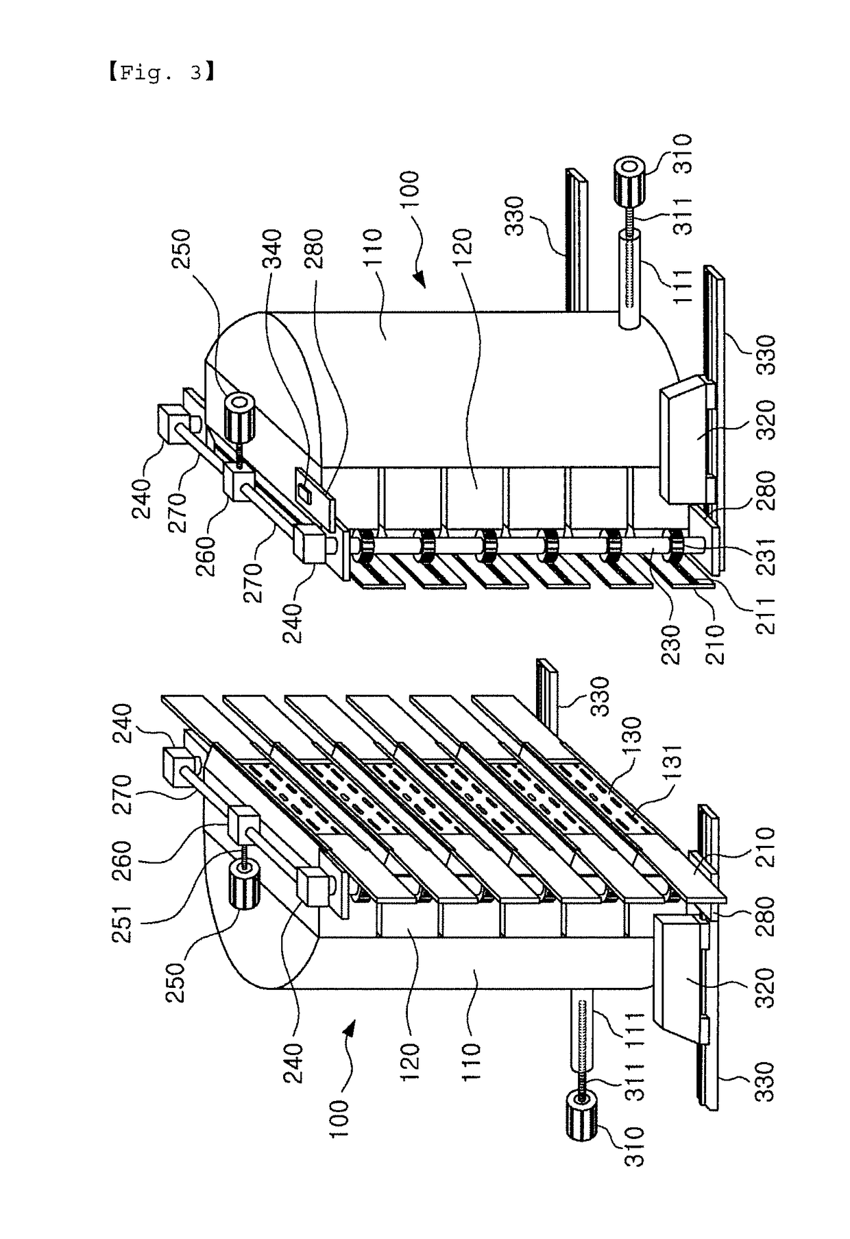
[0042]FIG. 3 is a perspective view illustrating a plated steel sheet cooling apparatus according to an exemplary embodiment in the present disclosure, and FIG. 4 is an exploded perspective view illustrating a spraying width varying unit in the apparatus for cooling a plated steel sheet in FIG. 3.

[0043]With reference to FIGS. 3 and 4, a plated steel sheet cooling apparatus according to an exemplary embodiment in the present disclosure may include a spraying unit spraying a cooling fluid onto a steel sheet 1, a spraying width varying unit and a spraying distance adjusting unit installed in the spraying unit. Here, a spraying width means a width of an entire area which is sprayed by a spraying unit.

[0044]Here, the spraying units are disposed on one side and the other side of the steel sheet 1, respectively and formed to spray a cooling fluid onto the steel sheet while opposing the driving steel sheet 1.

[0045]Such a spraying unit may include a main body 100 and spraying nozzles formed i...


PUM

PropertyMeasurementUnit
temperatureaaaaaaaaaa
widthaaaaaaaaaa
distanceaaaaaaaaaa

Abstract

A cooling apparatus for a plated steel sheet according to the present invention comprises: an injection means for injecting a cooling fluid while facing a steel sheet in progress; and an injection width varying means for varying the injection width of the cooling fluid so as to correspond to the width of the steel sheet, installed at the outside of the injection means so as to not interfere with the injection flow path of the cooling fluid.

Description

RELATED APPLICATIONS[0001]This application is the U.S. National Phase under 35 U.S.C. § 371 of International Application No. PCT / KR2014 / 011760, filed on Dec. 3, 2014, which in turn claims the benefit of Korean Patent Application No. 10-2014-0009808, filed on Jan. 27, 2014, the disclosure of which applications are incorporated by reference herein.TECHNICAL FIELD[0002]The present disclosure relates to a plated steel sheet cooling apparatus and, more particularly, to a plated steel sheet cooling apparatus for increasing cooling efficiency of a steel sheet and reducing vibrations thereof.BACKGROUND ART[0003]In recent years, demand for a plated steel sheet having improved corrosion resistance or the like, improved appearance, and specially used as a steel sheet for electronic products and vehicles, has increased. For example, an alloy-plated steel sheet has excellent spot weldability, corrosion resistance after coating, and coating adhesion. Thus, demand for such a steel sheet for use in...

Claims


Application Information

Patent Timeline
Patent Type & Authority Patents(United States)
IPC IPC(8): C23C2/00C23C2/40C23C2/28C23C2/04
CPCC23C2/28C23C2/40C23C2/04C23C2/003C23C2/26C23C2/00C23C2/29C23C2/50C23C2/0032C23C2/542
Inventor KIM, JUNG-KUKJEUNG, YEON-CHAE
Owner POHANG IRON & STEEL CO LTD
Learn More