Spherical multi-way fluid joint structure

A fluid joint, spherical technology, applied in the direction of pipes/pipe joints/fittings, branch lines, pipes, etc., can solve the problems of pressure loss, liquid leakage, flow capacity loss, etc., to reduce liquid flow resistance, simple and reasonable structure, Appearance-enhancing effect

Pending Publication Date: 2021-01-01
GUANGXI YUCHAI MASCH CO LTD
View PDF0 Cites 0 Cited by
  • Summary
  • Abstract
  • Description
  • Claims
  • Application Information

AI Technical Summary

Problems solved by technology

[0004] like figure 1 and figure 2 As shown, when the current articulated ring joint 10 or quick joint is used in practice, due to the overall layout of the engine pipeline 9, a flow channel with a 90° right-angle turn is usually formed, and such a structure will generate a large flow boundary Layer separation effect, thus causing obvious loss of flow capacity (pressure loss).

Method used


Image

  • Spherical multi-way fluid joint structure
  • Spherical multi-way fluid joint structure
  • Spherical multi-way fluid joint structure

Examples


Embodiment Construction

[0023] The specific embodiments of the present invention will be described in detail below in conjunction with the accompanying drawings, but it should be understood that the protection scope of the present invention is not limited by the specific embodiments.

[0024] Unless expressly stated otherwise, throughout the specification and claims, the term "comprise" or variations thereof such as "includes" or "includes" and the like will be understood to include the stated elements or constituents, and not Other elements or other components are not excluded.

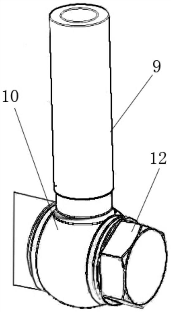
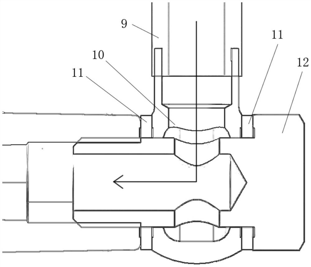
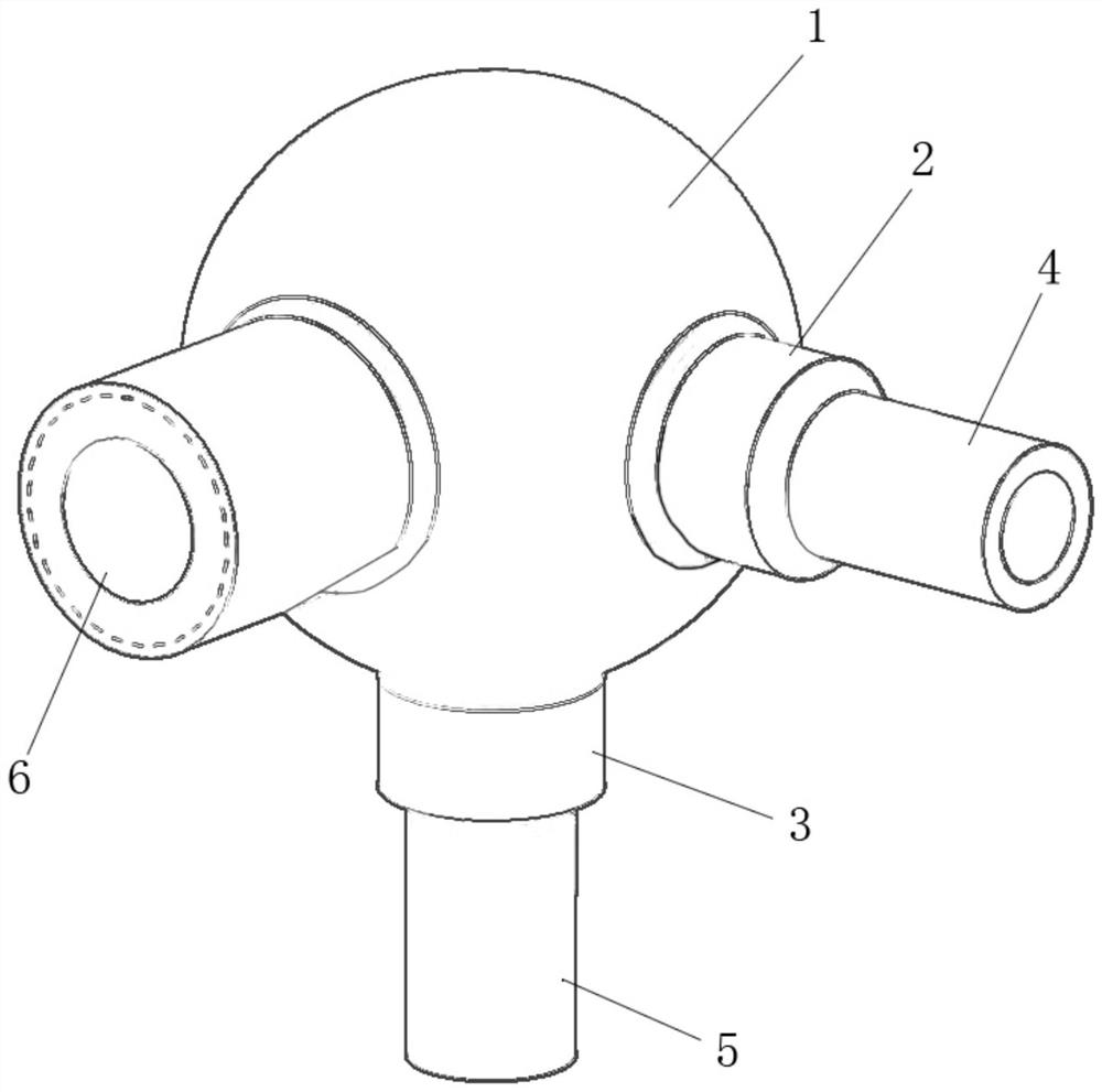
[0025] image 3 It is a three-dimensional structural schematic diagram of a spherical multi-way fluid joint structure according to an embodiment of the present invention; Figure 4 It is a schematic cross-sectional structure diagram of a spherical multi-way fluid joint structure according to an embodiment of the present invention.

[0026] Such as Figure 3 to Figure 4 As shown, a spherical multi-way fluid joint structur...


PUM


Abstract

The invention discloses a spherical multi-way fluid joint structure used for being connected with a pipeline of an engine. The spherical multi-way fluid joint structure comprises a sphere, a first boss, a second boss, a first joint and a second joint. The sphere is of a hollow structure and is provided with two first holes; one end of the first boss is fixedly connected with one first hole, and the first boss is provided with a first through hole; one end of the second boss is fixedly connected with the other first hole, and the second boss is provided with a second through hole; one end of the first joint is fixedly connected with the other end of the first boss, and the other end of the first joint is used for being fixedly connected with the pipeline of the engine; and one end of the second joint is fixedly connected with the other end of the second boss, and the other end of the second joint is used for being fixedly connected with the pipeline of the engine. Thus, the spherical multi-way fluid joint structure is simple and reasonable in structure, the liquid flowing resistance is reduced, and the leakage risk is reduced.

Description

technical field [0001] The invention relates to the technical field of joints related to engine working fluid pipelines, in particular to a spherical multi-way fluid joint structure. Background technique [0002] The working fluid of the engine includes various forms such as diesel oil, lubricating oil, coolant, etc. Most of these liquids need to flow and transfer between the engine parts through the pipeline, and the connection between the pipeline and the components needs to ensure the sealing effect. At the same time, it will produce a certain flow resistance for the working fluid. [0003] The pipe joints currently widely used in engines are usually hinged ring joint structures or quick joint structures. [0004] Such as figure 1 and figure 2 As shown, when the current articulated ring joint 10 or quick joint is used in practice, due to the overall layout of the engine pipeline 9, a flow channel with a 90° right-angle turn is usually formed, and such a structure will...

Claims


Application Information

Patent Timeline
IPC IPC(8): F16L41/02
CPCF16L41/02
Inventor 左俊杰罗名雄莫宗华
Owner GUANGXI YUCHAI MASCH CO LTD
Why Eureka
Try Eureka