
Fluid management assembly

A technology of fluid management and components, applied in the direction of valves absorbing fluid energy, engine components, valve details, etc., can solve the problems of increasing fluid flow resistance and unfavorable fluid flow, etc., to reduce fluid flow resistance and reduce pipeline connections Effect

Active Publication Date: 2020-12-25
ZHEJIANG SANHUA INTELLIGENT CONTROLS CO LTD
View PDF8 Cites 1 Cited by
  • Summary
  • Abstract
  • Description
  • Claims
  • Application Information

AI Technical Summary

Problems solved by technology

[0002] The functional components in the thermal management system are connected into a system through pipelines. Longer pipelines will relatively increase the fluid flow resistance. When the thermal management system is working, it is not conducive to the flow of fluid in the system.

Method used


Image

  • Fluid management assembly
  • Fluid management assembly
  • Fluid management assembly

Examples


Embodiment Construction

[0038] The fluid management components of the technical solution of the present invention can be in many ways, some of which can be applied to vehicle thermal management systems, and some can also be applied to other thermal management systems such as household thermal management systems or commercial thermal management systems, as follows A specific vehicle fluid management assembly will be described with reference to the accompanying drawings as an example.

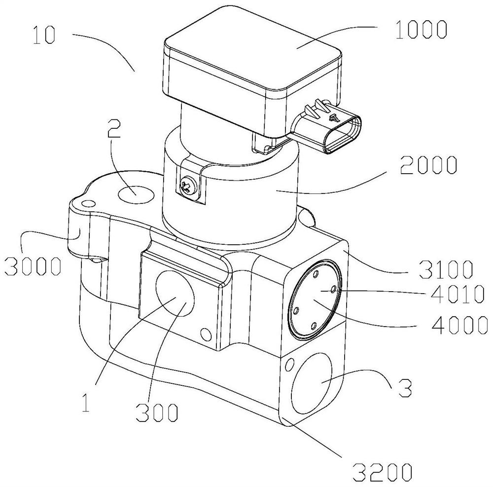
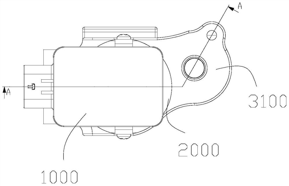
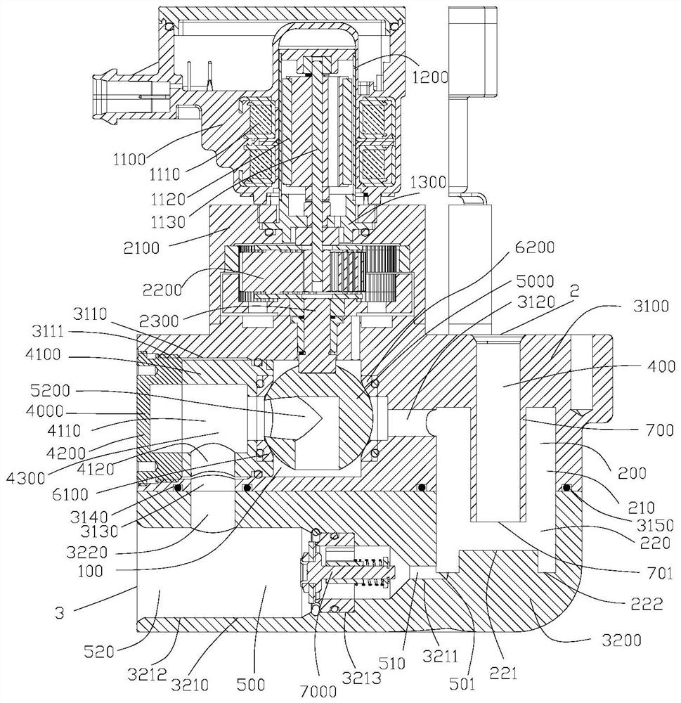
[0039] see Figure 1-Figure 5 , the fluid management assembly 10 includes a control part, a transmission device 2000, a valve body 3000, and a first valve core 5000. In the technical solution of this embodiment, the control part is a drive mechanism 1000, and the transmission device 2000 is located between the drive mechanism 1000 and the valve body 3000. Among them, the driving mechanism 1000 includes a motor part 1100, a bushing 1200 and a connecting seat 1300, one end of the connecting seat 1300 is fixedly connected ...


PUM


Abstract

The invention discloses a fluid management assembly. The fluid management assembly comprises a valve body, a first cavity, a second cavity, a first flow channel, a second flow channel, a third flow channel and a fourth flow channel; openings are formed in the positions, on the outer wall of the valve body, of the first flow channel, the second flow channel and the third flow channel; the valve body is provided with the second cavity, the second flow channel and the first channel, and the first channel can communicate with the first cavity and the second cavity. The fluid management assembly isprovided with the multiple channels, the first cavity and the second cavity, pipeline connection between corresponding functional components can be reduced, and fluid flow resistance can be relatively reduced conveniently.

Description

【Technical field】 [0001] The present invention relates to the technical field of fluid management. 【Background technique】 [0002] The functional components in the thermal management system are connected into a system through pipelines. Longer pipelines will relatively increase the fluid flow resistance. When the thermal management system is working, it is not conducive to fluid flow in the system. 【Content of invention】 [0003] The object of the present invention is to provide a fluid management assembly to help solve the above problems. [0004] A fluid management assembly, including a valve body and a first valve core, the fluid management assembly also includes a first cavity and a second cavity, the wall forming the second cavity includes the inner wall of the valve body; the first valve core is located in the The first cavity, the first spool can rotate in the first cavity, the first spool has a conduction channel, the fluid management assembly includes a throttle ...

Claims


Application Information

Patent Timeline
IPC IPC(8): F16K5/06F16K5/08F16K5/12F16K5/20F16K27/06F16K31/04F16K31/53F16K47/04F16K47/08
CPCF16K5/0605F16K5/20F16K5/08F16K31/04F16K31/53F16K27/067F16K47/045F16K47/08F16K5/12
Inventor 不公告发明人
Owner ZHEJIANG SANHUA INTELLIGENT CONTROLS CO LTD
Learn More