Automotive combination sensor

a combination sensor and automotive technology, applied in the direction of electrical control, process and machine control, instruments, etc., can solve the problems of inaccuracy of egr estimation, lagging map reading, inaccuracy of map reading, etc., to improve fuel economy, improve fuel economy, and improve fuel economy

Inactive Publication Date: 2014-10-30
FORD GLOBAL TECH LLC
View PDF4 Cites 12 Cited by
  • Summary
  • Abstract
  • Description
  • Claims
  • Application Information

AI Technical Summary

Benefits of technology

[0002]Engine control systems employ exhaust gas recirculation (EGR) mechanisms to regulate exhaust emissions and improve fuel economy. External EGR is also used by automotive manufacturers to improve fuel economy. EGR improves fuel economy by ...

Problems solved by technology

However, the inventors herein have identified potential disadvantages with such approaches.
Such operation may result in the MAP sensor either being positioned away from a desired measurement location in the intake manifold (resulting in potentially inaccurate MAP readings), or a measurement tube enabling the MAP sensor to be positioned at a remote location (resulting in lagging MAP readings).
In one example, i...

Method used


Image

  • Automotive combination sensor
  • Automotive combination sensor
  • Automotive combination sensor

Examples


Embodiment Construction

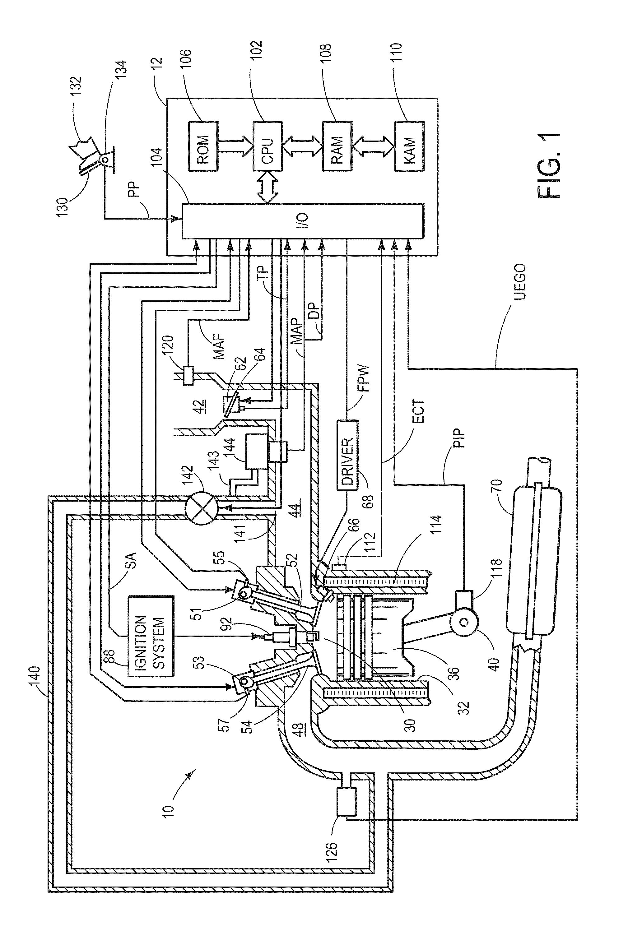
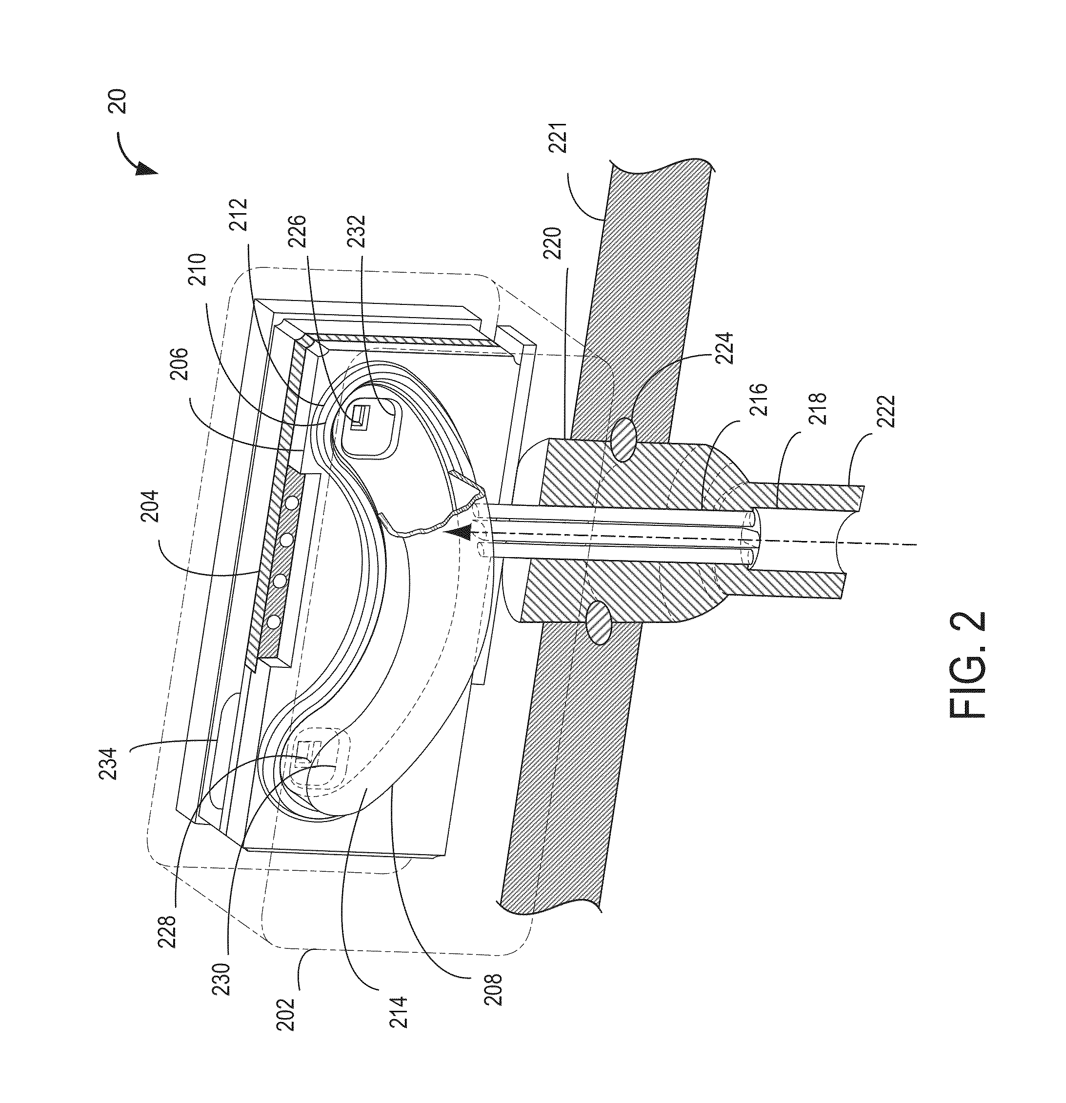
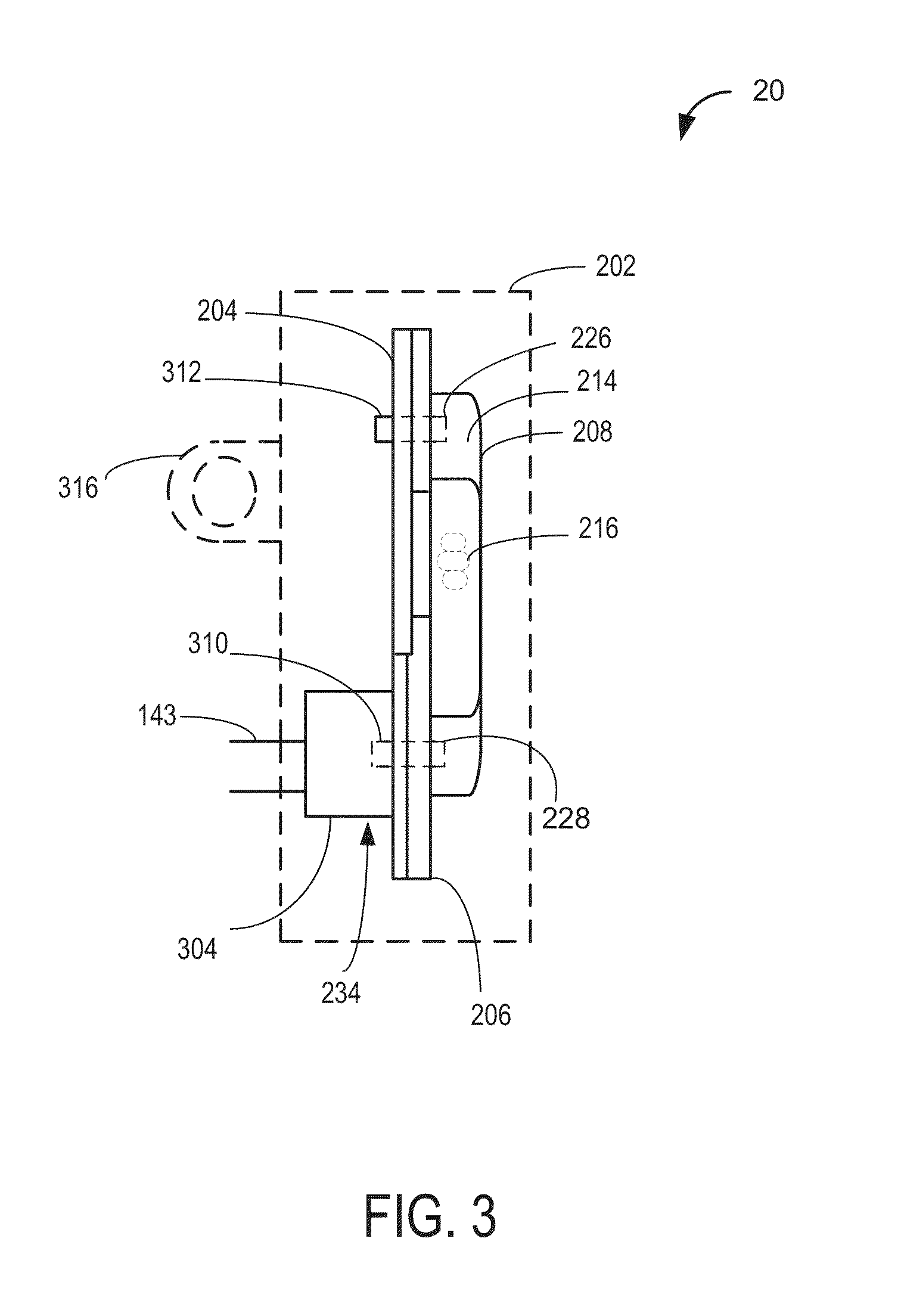
[0016]Methods and systems are provided for reducing air mass estimation error in engine systems (such as engine system of FIG. 1) that utilize speed density air estimation and exhaust gas recirculation strategies during transient and steady state conditions. A combination sensor module, described at FIGS. 2 and 3, may be employed in the engine system of FIG. 1, as described at FIGS. 4A-4B, to reduce errors in exhaust gas recirculation mass determination. Further, a feedback regulation mechanism, as illustrated in a block diagram at FIG. 5, may be utilized to control exhaust gas recirculation flow. A controller, such as the controller of FIG. 1, may be configured to perform a control routine, such as the example routine of FIG. 6 to estimate air mass based on exhaust gas recirculation mass using the combinational sensor of FIGS. 2-4, and the mechanism of FIG. 5.

[0017]FIG. 1 is a schematic diagram showing one cylinder of multi-cylinder engine 10, which may be included in a propulsion ...


PUM


Abstract

Systems are provided for EGR mass and air mass estimation during steady state and transient operations. By utilizing a combination sensor comprising of a manifold absolute pressure sensing element and a differential pressure sensing element sharing a common pressure chamber with connections to the intake manifold, errors in EGR mass estimation may be reduced.

Description

FIELD[0001]The present disclosure relates to estimation of exhaust gas recirculation and air charge during steady state and transient operation conditions.BACKGROUND AND SUMMARY[0002]Engine control systems employ exhaust gas recirculation (EGR) mechanisms to regulate exhaust emissions and improve fuel economy. External EGR is also used by automotive manufacturers to improve fuel economy. EGR improves fuel economy by reducing pumping losses at part throttle (that is, EGR can lower engine pumping work by increasing intake manifold pressure). Further, by adding cooled EGR, the tendency for spontaneous ignition initiated via spark-ignited combustion, may be reduced.[0003]EGR involves recirculating exhaust gas from the exhaust manifold into the intake manifold through a flow control valve placed in the path of the EGR flow in between the exhaust manifold and the intake manifold. In doing so, exhaust gases are added to the air-fuel mixture. EGR amount may be calculated by a controller bas...

Claims


Application Information

Patent Timeline
IPC IPC(8): F02D21/08
CPCF02D21/08F02D2021/083F02D41/0072F02D41/0052F02D2200/0406Y02T10/40
Inventor GATES, FREEMAN CARTERVROMAN, DENNISNADDAF, FADI MAROUNMCROY, GITANJLI
Owner FORD GLOBAL TECH LLC
Why Eureka
Try Eureka