

Car nameplate with a backlight
a technology of car nameplates and backlights, applied in the field of car nameplates, can solve problems such as low light efficiency
- Summary
- Abstract
- Description
- Claims
- Application Information
AI Technical Summary
Benefits of technology
Problems solved by technology
Method used
Image

Examples
Embodiment Construction
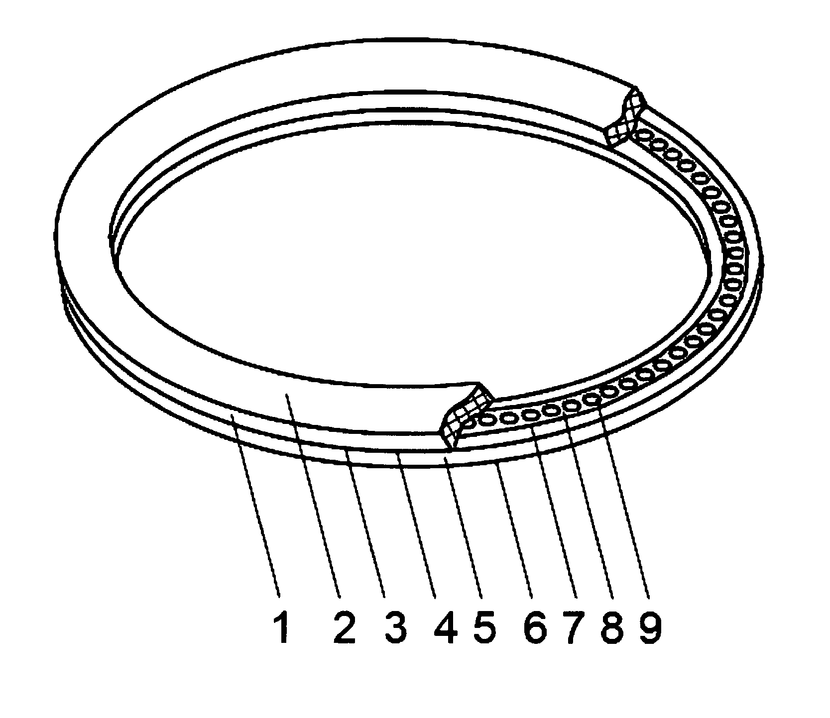
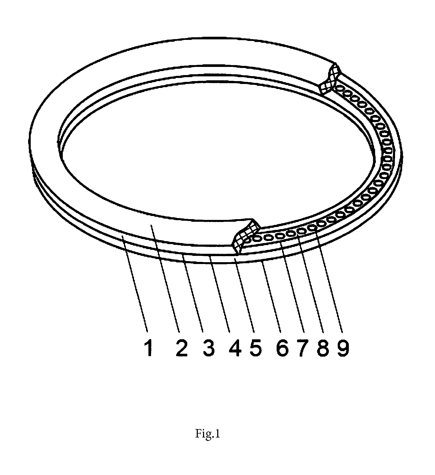
[0009]The present invention comprises an illuminated vehicle nameplate having a main element with opposite locations of an outer surface and a first inner surface, a clear element with opposite locations of a second inner surface and a connecting surface, a light source, the main element made of clear material, the main element of the first inner surface connected with the second inner surface of the clear element, the light source being made in the form of an LED strip and located between the main element and the connecting surface, and a channel being made in the clear element on the side of the second inner surface and the light source being located in the given channel.
[0010]The FIGURE (FIG. 1) shows: main element 1, outer surface 2, first inner surface 3, second inner surface 4, clear (or translucent) element 5, connecting surface 6, channel 7, strip 8, and light source 9.
[0011]The main features of the device consist of the main element 1, clear element 5, light source 9, and f...
PUM
 Abstract
Description
Claims
Application Information