Modular system

a module system and modular technology, applied in the field of modules, can solve the problems of affecting the use of modules, not providing specifics, and the assembly method of the system is rather complicated, and achieve the effect of simple and secure way

Inactive Publication Date: 2014-11-20
HDN HLDG APS
View PDF17 Cites 3 Cited by
  • Summary
  • Abstract
  • Description
  • Claims
  • Application Information

AI Technical Summary

Benefits of technology

[0004]The aspect of the present invention is to provide a system without the disadvantages of the above system or to provide a useful alternative. The invention achieves inter alia a simple system for joining / connecting modules such that the modules are fastened to each other in a unique way, but also very simple and secure way.

Problems solved by technology

The assembly method of the system is rather complicated and does not provide any specific flexibility in the assembly as a compact and uniform partition construction is provided by this method, in which the partition is produced by boxes abutting boxes.
Tools are required for assembling the system, and as the joining elements are placed at the middle of the boards, the use thereof is obviously impaired, regardless of whether the modular system is to be used as a book case, where the books collide with the large nut or whether the system is to be used as a table, where the joining elements disturb the plane surface.

Method used


Image

  • Modular system
  • Modular system
  • Modular system

Examples


second embodiment

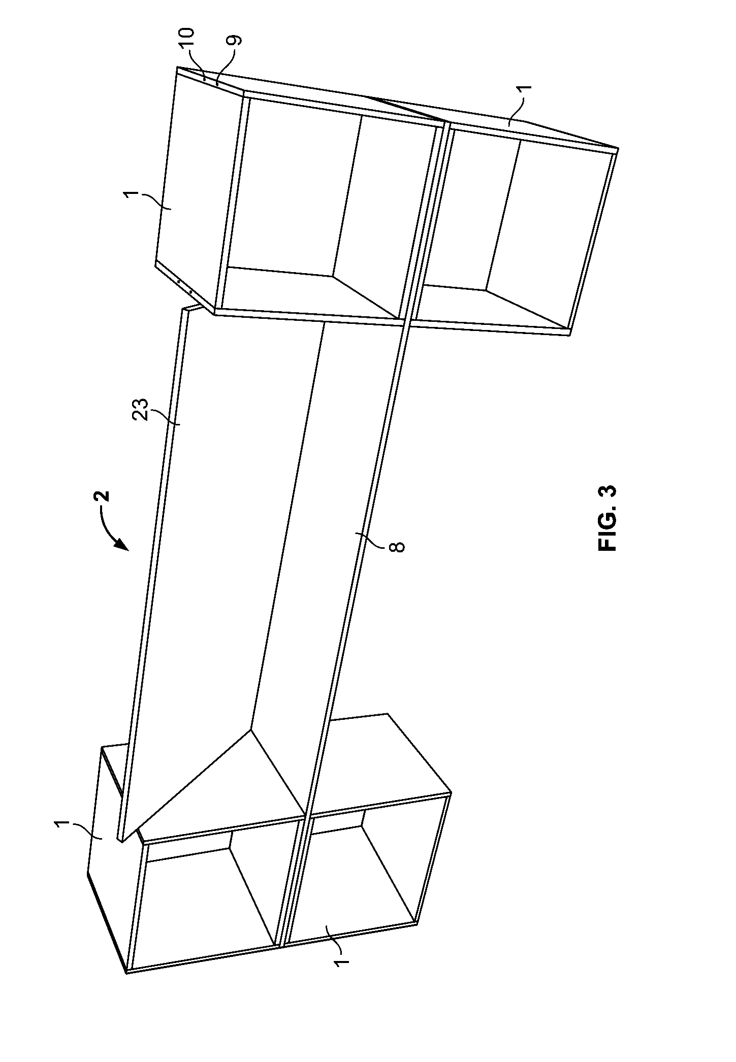
[0038]FIG. 3 shows a modular system (2) according to the invention as this comprises a very long extension panel (8), said extension panel being rectangular and extending from the placement between a left module rack consisting of an upper module (1) and a lower module (1) wherebetween the extension panel (8) is arranged and secured with its fastening means as stated above with reference to FIG. 2. At the other end, the extension panel (8) is also placed between a module rack, i.e. the right side is placed in a corresponding way between upper and lower modules and likewise with its fastening means (12) fixed to their positioning means (9). This way a less compact shelf system is achieved and an additional shelf is provided without having to use several modules (1) which are the expensive part. Further, it is possible to place a loose board (23) on top of the long rectangular extension panel (8), said loose board thus being able to constitute a desk top with extra width. If after the...

third embodiment

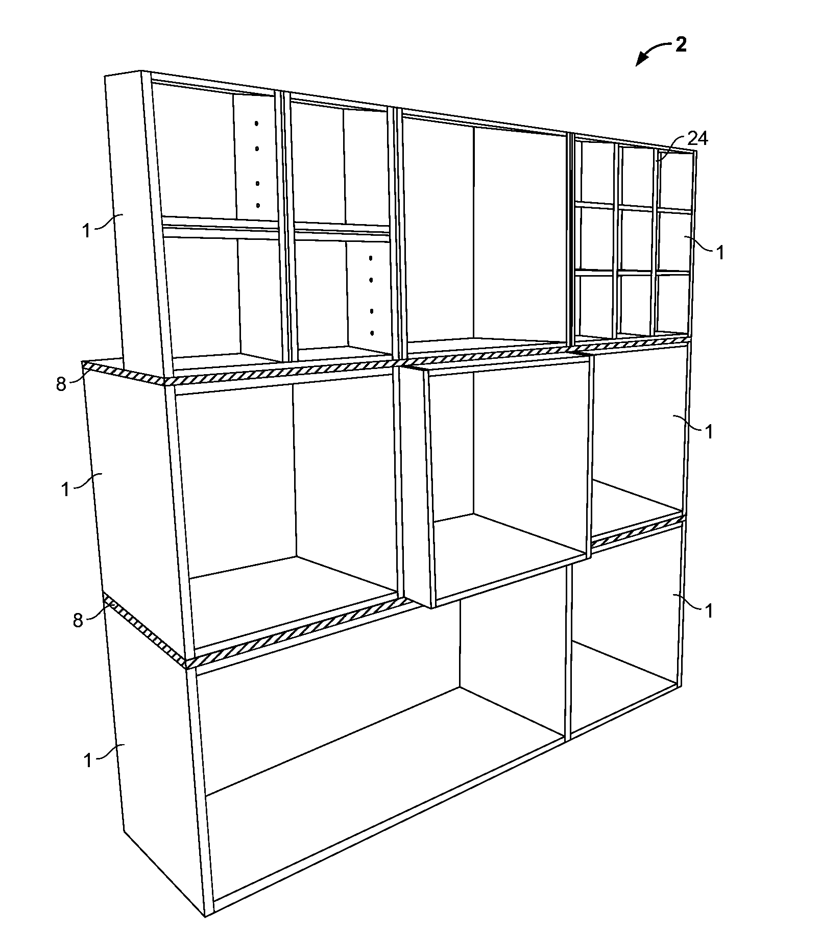
[0039]FIG. 4 shows a modular system (2) according to the invention which is also constructed by the previously described modules (1) and extension panels (8). In this case the modules (1) are shaped in rectangular and square units, but with very different sizes, and as is also evident, the actual modules may naturally also be offset in relation to each other so that a front surface of a module can be offset in relation to the front surface of the module below. Inside the individual modules it is also possible to insert a partition (24) for separating each individual module into even smaller compartments.

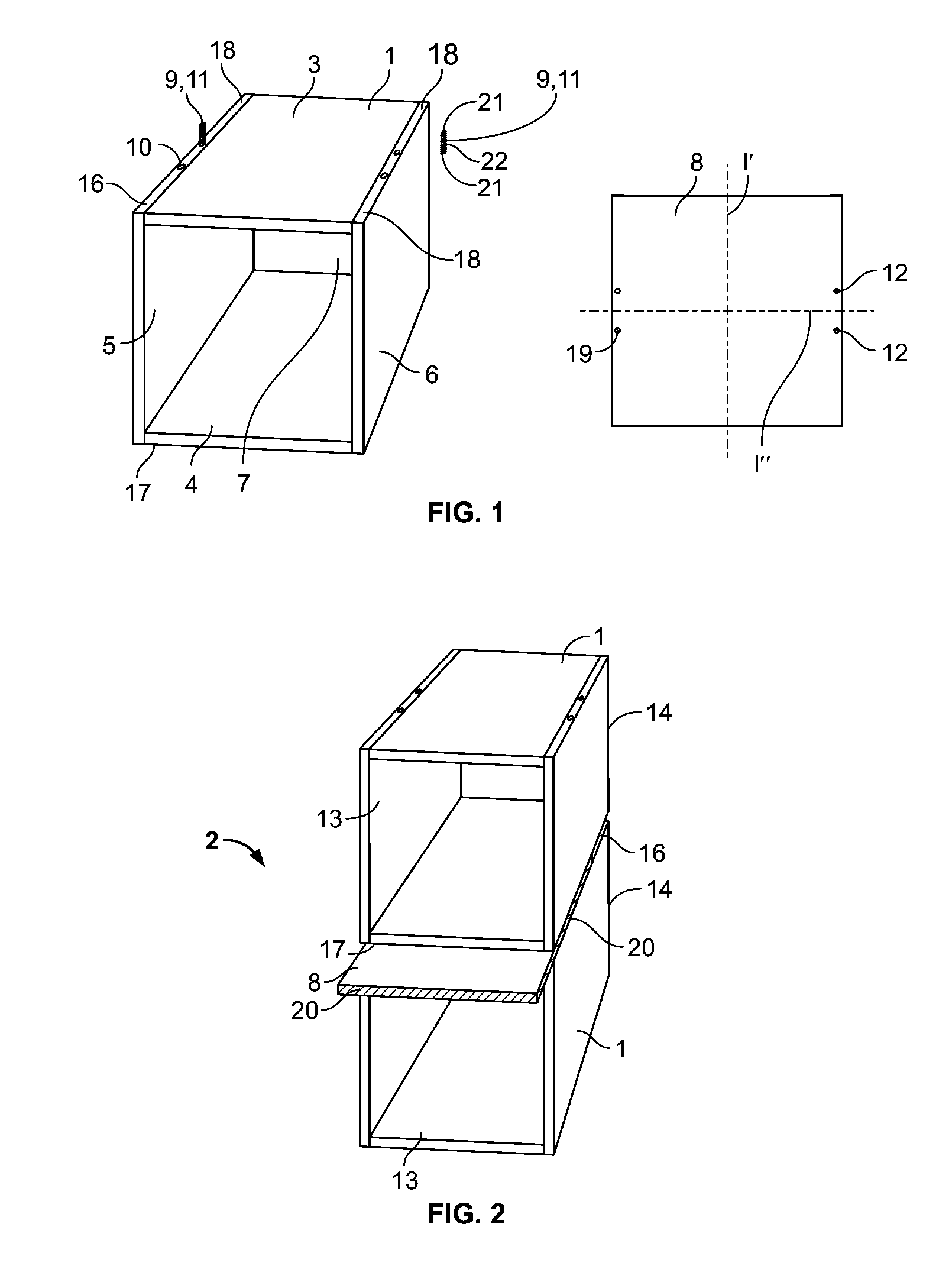
[0040]It is noted that the shelf top panel (3) and the shelf bottom panel (4) in each module (1) have the same geometry and dimension and are rectangular or square boards.

[0041]Each module (1) is comprised by boards being assembled with known joining elements as is known from other types of furniture which can be assembled at home. By assembly of the square or rectangular boards, the...


PUM

PropertyMeasurementUnit
distanceaaaaaaaaaa
distanceaaaaaaaaaa
diameteraaaaaaaaaa

Abstract

Modular system (2) comprising at least two modules (1), said modules comprising a shelf top panel (3) and an oppositely placed shelf bottom panel (4), said two panels being mutually connected by a first shelf side panel (5) and an oppositely placed second shelf side panel (6) for providing a box-shaped module (1). Said module (1) comprises positioning means 89) adapted to position one module (1) to a second module (1), and the modular system (2) also comprises at least one extension panel (8), said extension panel (8) comprising fastening means adapted to engage with the positioning means, whereby the extension panel is secured.

Description

TECHNICAL FIELD[0001]The invention relates to a modular system comprising at least to modules, said modules comprising a shelf top panel and an oppositely placed shelf bottom panel, said two panels being mutually connected by a first shelf side panel and an oppositely placed second shelf side panel for providing a box-shaped module comprising an outer top surface and an outer bottom surface, said modular system comprising positioning means adapted for positioning and engaging with the top surface of a module and with the bottom surface of a second module, and said modular system further comprising at least an extension panel comprising an upper extension surface and a lower extension surface, further the upper extension surface faces the bottom surface, further the lower extension surface faces the top surface, said extension panel comprising fastening means adapted so as to engage with the positioning means, whereby the extension panel is secured.BACKGROUND[0002]US 2007 / 0158347 des...

Claims


Application Information

Patent Timeline
Patent Type & Authority Applications(United States)
IPC IPC(8): A47B47/00
CPCA47B47/0091A47B47/0025A47B87/0292F16B12/24
Inventor NIELSEN, JORGEN
Owner HDN HLDG APS
Why Eureka
Try Eureka