Time of flight camera unit and optical surveillance system

a camera unit and optical surveillance technology, applied in the field of time of flight, can solve the problems of system cost, two complete tof cameras, and invisible areas 214/b> of objects, and achieve the effect of simple and secure way

Active Publication Date: 2014-11-04
ROCKWELL AUTOMATION SWITZERLAND
View PDF20 Cites 17 Cited by
  • Summary
  • Abstract
  • Description
  • Claims
  • Application Information

AI Technical Summary

Benefits of technology

[0013]According to one embodiment of the present innovation, a time of flight, TOF, camera unit for an optical surveillance system and at least one mirror, which at least partly deflects the emitted radiation into at least one second plane extending across to the first plane and deflects the radiation reflected from the second plane back to the radiation detecting unit, detects a three-dimensional image of directly visible and shadowed parts of the object in a particularly simple and secure way. In particular, only one TOF camera is needed which therefore obviates the necessity of synchronizing a plurality of TOF cameras.
[0015]According to one feature of the present invention, the radiation emitting unit comprises at least one light-emitting diode, which represents a particularly efficient and easily controllable way of providing an illumination of the surveillance area.
[0017]The signal processing unit according to one embodiment of the present invention preferably is operable to define and evaluate a first depth level representing the area directly illuminated by said radiation emitting unit, and at least a second depth level representing the area illuminated by said radiation emitting unit via said at least one mirror. The images corresponding to these two depth levels are combined for generating a three-dimensional image of the total surveillance area including shadowed parts of objects to be detected. By restricting the signal processing to these depth levels, background signals can be effectively suppressed.

Problems solved by technology

A problem arises when an object to be detected 210 enters the detection field.
However, due to shading effects with the known surveillance system 200 the problem occurs that invisible areas 214 of the object 210 remain.
However, the system is costly, requiring two complete TOF cameras and the synchronization of the generated images is difficult.
However, as this is known for laser scanners, the viewing field of this arrangement is only in one plane and no three-dimensional image can be generated from the retrieved data.
Furthermore, the signal processing routine proposed in this document is only working in combination with a moving laser scanning beam.
Furthermore, the arrangement according to U.S. Pat. No. 5,903,355 is not suitable for short-distance applications.

Method used


Image

  • Time of flight camera unit and optical surveillance system
  • Time of flight camera unit and optical surveillance system
  • Time of flight camera unit and optical surveillance system

Examples


Embodiment Construction

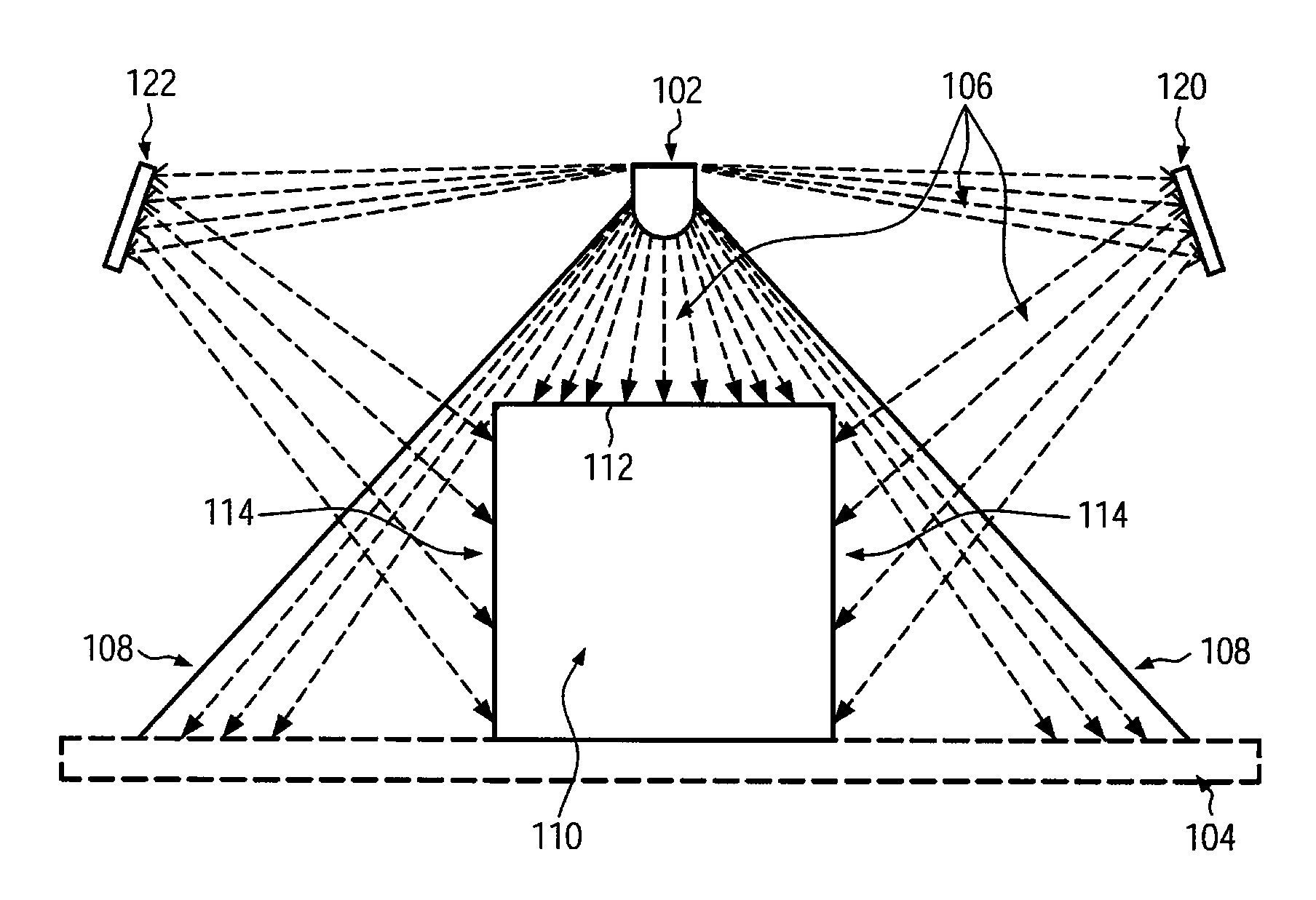
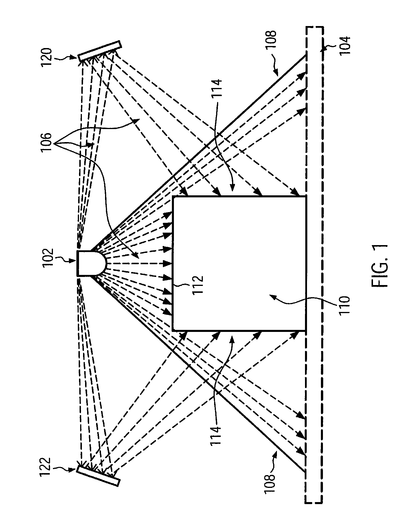
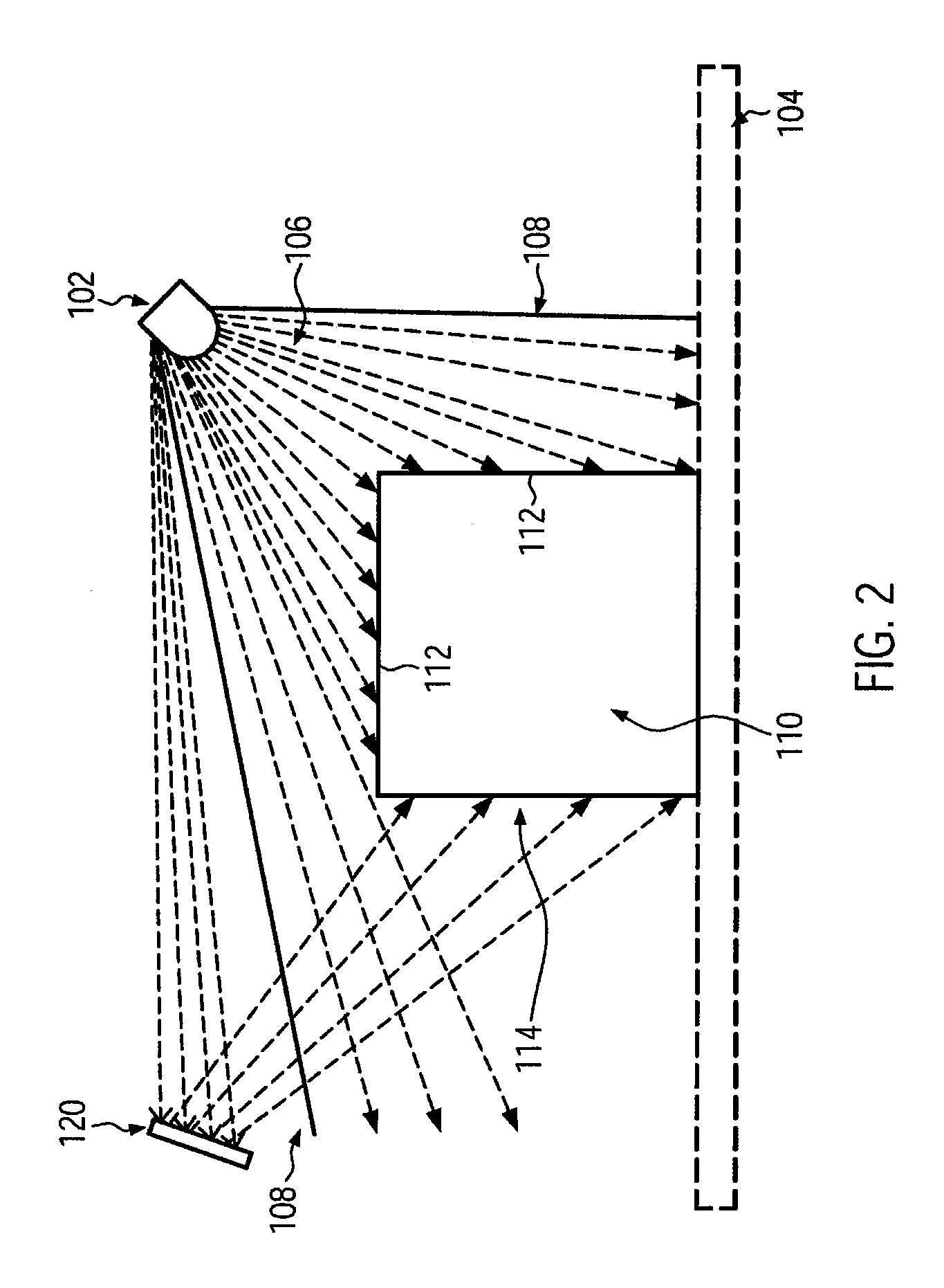
[0032]Referring now to FIG. 1, a time of flight, TOF, camera 102 is combined with two mirrors 120 and 122 for deflecting the radiation 106 sent from the TOF camera 102 to an object 110 and vice versa. Although in FIG. 1 only the emitted radiation is depicted, of course also the reflected radiation from the object and the background runs along the shown path of rays, only with opposite direction. The radiation usually is emitted by light emitting diodes, LED, or infrared radiation emitting diodes, IRED.

[0033]The use of the mirrors 120, 122 allows measuring all surfaces of a three-dimensional body with one single TOF camera 102. The radiation beams 106, which are deflected by the mirrors 120, 122, are subjected to an additional electromagnetic phase shift of π by each reflection at the mirror surface resulting in a total of 2 π, when they are received back at the detector of the TOF camera 102. However, the phase of the modulation is not influenced by the reflection. Consequently, the...


PUM


Abstract

A time of flight, TOF, camera unit for an optical surveillance system and an optical surveillance system comprising such a TOF camera is disclosed. The TOF camera unit comprises a radiation emitting unit for illuminating a surveillance area defined by a first plane, a radiation detecting unit for receiving radiation reflected from said surveillance area and for generating a three-dimensional image from said detected radiation, and at least one mirror for at least partly deflecting said emitted radiation into at least one second plane extending across to said first plane and for deflecting the radiation reflected from said second plane to the radiation detecting unit. The TOF camera and the at least one mirror may be arranged on a common carrier element.

Description

CROSS-REFERENCE TO RELATED APPLICATIONS[0001]This application claims priority to European Patent Application No. EP 10004001, titled Time of Flight Camera Unit and Optical Surveillance System and filed Apr. 15, 2010, the entire contents of which is incorporated herein by reference.BACKGROUND OF THE INVENTION[0002]The subject matter disclosed herein relates to a time of flight, TOF, camera unit for an optical surveillance system and to an optical surveillance system comprising such a TOF camera.[0003]During the last few years, the first all-solid state three-dimensional cameras (3-D cameras) based on the time of flight (TOF) principle became available on the market. 3-D cameras or sensors based on the time of flight principle acquire distance information from objects in a scene being imaged. Distance information is produced independently at each pixel of the camera sensor. As for instance described in U.S. Pat. No. 6,323,942, a TOF system emits optical energy and determines how long ...

Claims


Application Information

Patent Timeline
Patent Type & Authority Patents(United States)
IPC IPC(8): G01S17/89G01B11/245G06T7/00G01B11/22G01S17/87H04N13/02G01S17/36G01B11/24G01S17/894
CPCG06T7/0065G01S17/87G01S17/36G01S17/89G01B11/245G01B11/24G01B11/22H04N13/0214G06T2207/10012G06T2207/30232G01S17/42G06T7/55H04N13/214G01S17/894
Inventor MEINHERZ, CARL
Owner ROCKWELL AUTOMATION SWITZERLAND
Why Eureka
Try Eureka