Antenna device and electronic apparatus

a technology of electronic equipment and antenna, which is applied in the field of mobile electronic equipment, can solve the problems of annoy the wearer of the antenna, the size of the element itself is likely to be large, and the antenna module is likely to become large, and achieves the effect of wide directivity

Active Publication Date: 2014-12-18
MURATA MFG CO LTD
View PDF2 Cites 2 Cited by
  • Summary
  • Abstract
  • Description
  • Claims
  • Application Information

AI Technical Summary

Benefits of technology

[0007]An object of the present invention is to provide antenna devices having wide directivity in a state of being attached to a garment, a person's body, or the like, and electronic apparatuses provided with the stated antenna devices.
[0015]According to the present invention, an antenna device having wide directivity in a state where an electronic apparatus is attached to a garment, a person's body, or the like, and the stated electronic apparatus are obtained.

Problems solved by technology

In addition, because the antenna is a patch antenna, size of the element itself is likely to be large.
This makes the antenna module likely to become large when the circuit side is integrated therein.
Furthermore, thickness of the antenna in a thickness direction thereof becomes large, which can annoy the wearer of the antenna.

Method used


Image

  • Antenna device and electronic apparatus
  • Antenna device and electronic apparatus
  • Antenna device and electronic apparatus

Examples


first embodiment

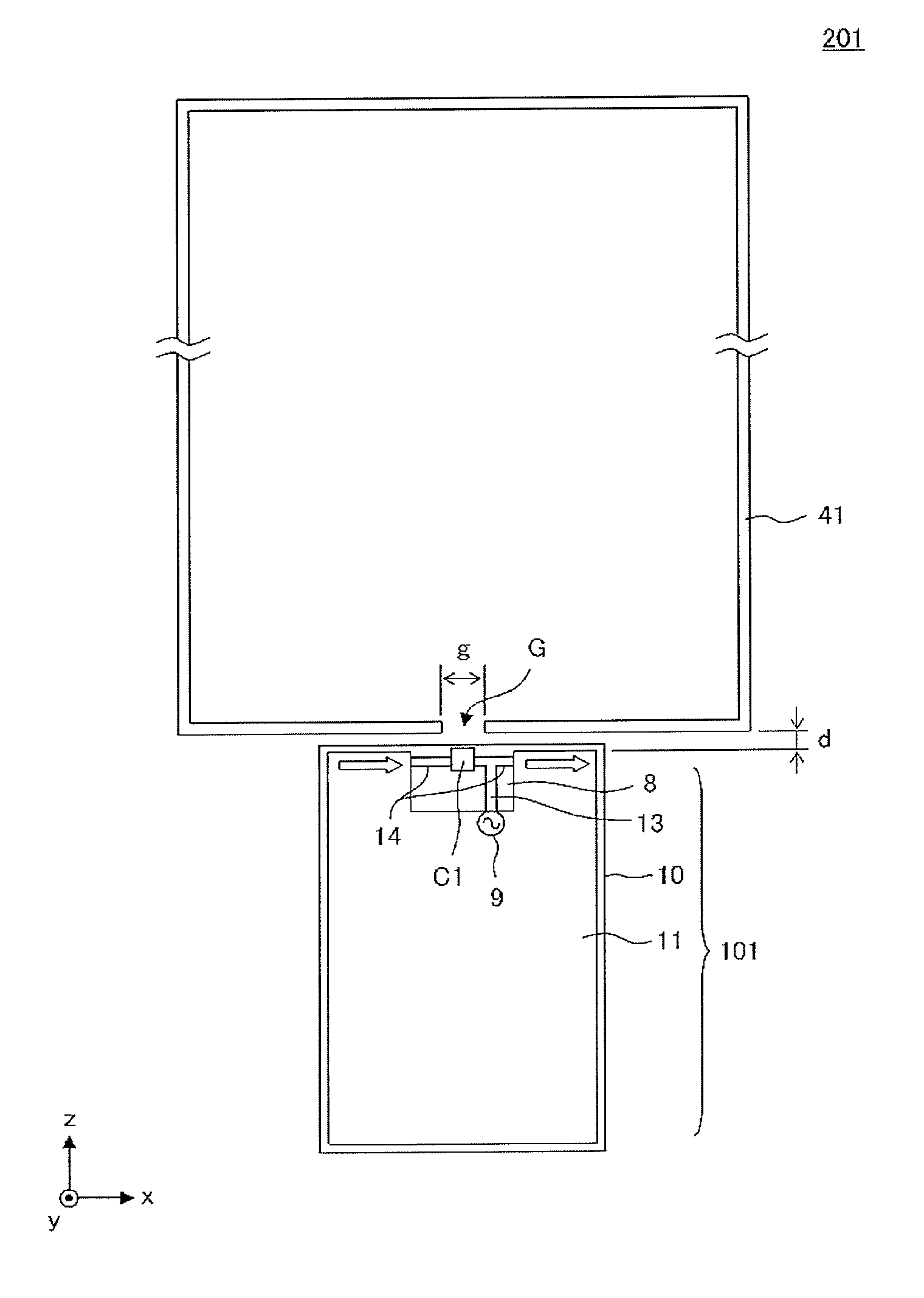
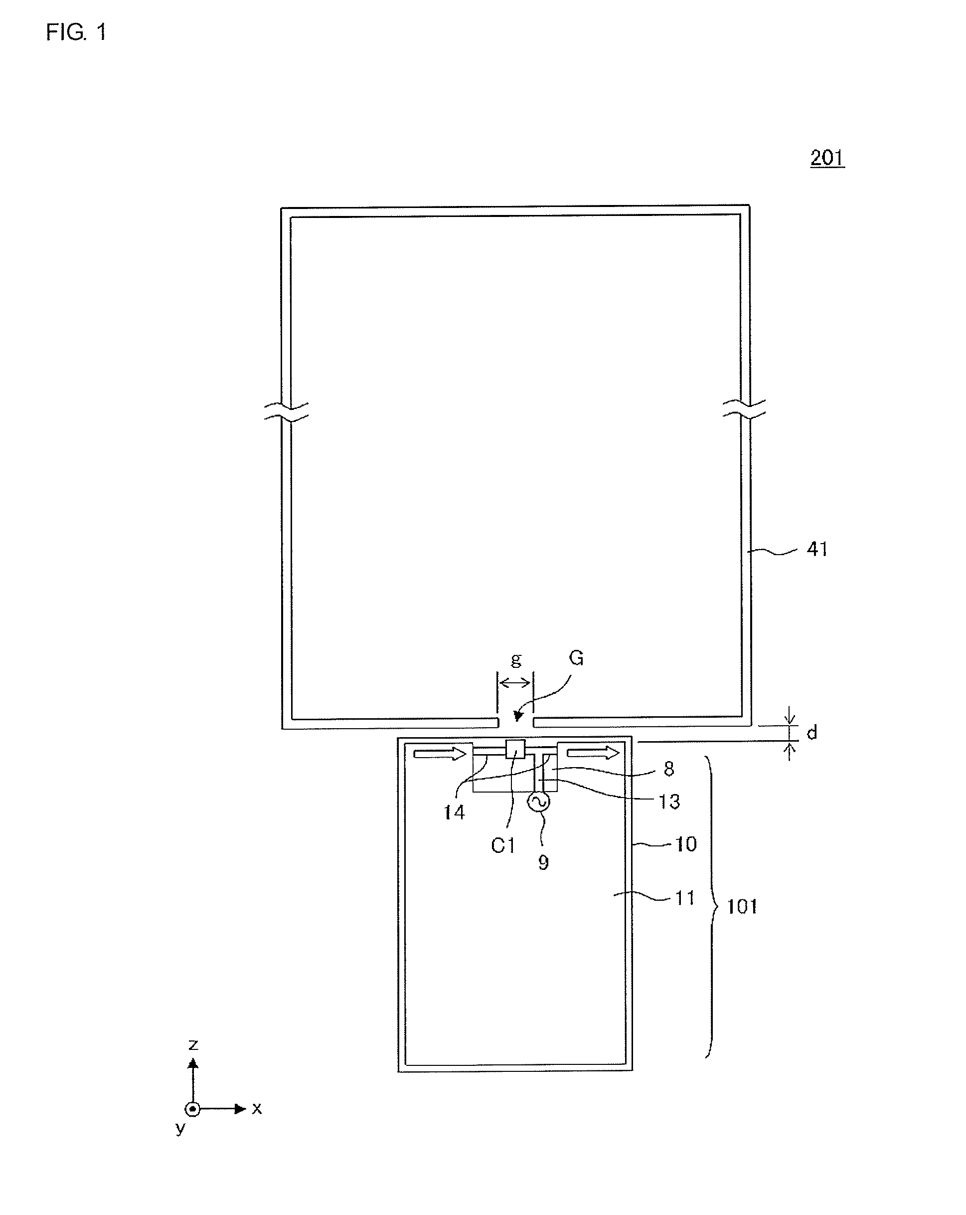
[0039]FIG. 1 is a diagram illustrating the principal constituent elements of an antenna device 201 according to a first embodiment. In FIG. 1, the antenna device 201 includes a communication module 101 and a loop-shaped conductor 41. The communication module 101 has a substrate 10 on which an approximately rectangular ground conductor 11 is formed. A non-ground region 8 is provided along one side of the ground conductor 11. A transmission line 13 and a radiation element 14 are formed in the non-ground region 8. Further, a capacitance element C1 is connected to the radiation element 14, and the transmission line 13 is connected to a feeding point of the radiation element 14. A feeder circuit 9 is provided on the substrate 10 and power is fed to the radiation element 14 by the feeder circuit 9 via the transmission line 13.

[0040]Feeding the power to the radiation elements 14 causes the radiation element 14 to resonate. A current is induced in the ground conductor 11 in the same manner ...

second embodiment

[0054]FIG. 7 is a diagram illustrating the principal constituent elements of an antenna device 202 according to a second embodiment. In FIG. 7, the antenna device 202 includes a communication module 102 and the loop-shaped conductor 41. The communication module 102 has the substrate 10 on which the approximately rectangular ground conductor 11 is formed. The non-ground region 8 is provided along one side of the ground conductor 11. A radiation element 15 is formed in the non-ground region 8. The feeder circuit 9 is provided on the substrate 10, and power is fed to the radiation element 15 by the feeder circuit 9. The radiation element 15 acts as a radiation element of a monopole antenna. Further, a portion near an open end of the radiation element 15 and an end portion EP1 of the loop-shaped conductor 41 which is near the gap G and is in the vicinity of the above portion of the radiation element 15, mainly form electric field coupling. Although intensity of electric field is weak in...

third embodiment

[0059]FIG. 10 is a diagram illustrating the principal constituent elements of an antenna device 203 according to a third embodiment. In FIG. 10, the antenna device 203 includes a communication module 103 and the loop-shaped conductor 41. The communication module 103 has the substrate 10 on which the approximately rectangular ground conductor 11 is formed. The non-ground region 8 is provided along one side of the ground conductor 11. Radiation elements 16a and 16b are formed in the non-ground region 8. The feeder circuit 9 is provided on the substrate 10, and the radiation element 16a is fed with power by the feeder circuit 9. The radiation element 16b is a non-power fed radiation element, and one end thereof is connected to the ground conductor 11 (grounded) while the other end is open. The open end of the radiation element 16b is near an open end of the radiation element 16a; the radiation element 16b is fed with power through capacitance generated between both the open ends. The r...


PUM


Abstract

An antenna device includes a communication module and a loop-shaped conductor. The communication module has a substrate on which an approximately rectangular ground conductor is formed. A non-ground region is provided along one side of the ground conductor. A transmission line and a radiation element are formed in the non-ground region. Further, a capacitance element is connected to the radiation element, and the transmission line is connected to a feeding point of the radiation element. The loop-shaped conductor includes in part a gap that is positioned near the radiation element. With this, an antenna device to be provided in an electronic apparatus having wide directivity in a state of being attached to a garment, a person's body, or the like, and the stated electronic apparatus are configured.

Description

CROSS REFERENCE TO RELATED APPLICATIONS[0001]The present application is a continuation of International Application No. PCT / JP2013 / 053309, filed Feb. 13, 2013, which claims priority to Japanese Patent Application No. 2012-047549, filed Mar. 5, 2012, the entire contents of each of which are incorporated herein by reference.FIELD OF THE INVENTION[0002]The present invention relates to mobile electronic apparatuses configured to perform wireless communications, in particular, electronic apparatuses capable of performing wireless communications in a state of being attached to a garment, a person's body, or the like, and antenna devices provided in the stated electronic apparatuses.BACKGROUND OF THE INVENTION[0003]An antenna device of an electronic apparatus capable of performing wireless communications in a state of being attached to a garment, a person's body, or the like is disclosed in Patent Document 1.[0004]FIG. 23 is a diagram illustrating a usage state of the antenna device disclo...

Claims


Application Information

Patent Timeline
Patent Type & Authority Applications(United States)
IPC IPC(8): H01Q1/27H01Q1/48H01Q1/50H01Q7/00
CPCH01Q1/273H01Q1/50H01Q1/48H01Q7/00
Inventor ONAKA, KENGOTANAKA, HIROYA
Owner MURATA MFG CO LTD
Why Eureka
Try Eureka