Boundary microphone

a microphone and boundary technology, applied in the field of flat boundary microphones, can solve the problems of inconvenient change of directivity characteristics, and achieve the effect of not deteriorating narrow directivity

Inactive Publication Date: 2017-05-18
AUDIO-TECHNICA
View PDF48 Cites 1 Cited by
  • Summary
  • Abstract
  • Description
  • Claims
  • Application Information

AI Technical Summary

Benefits of technology

[0016]According to the present invention, a sound wave is taken in the tubular groove corresponding to the acoustic tube through a gap (side opening for sound wave) between the peripheral edge part of the cover plate and the upper face of the base plate. Acoustic resistance of the side opening for sound wave is set to be the acoustic resistance with the thin air layer formed by the spacer that is composed of the water repellent thin film material. Hence, even when liquid enters the boundary microphone from the outside, the liquid does not penetrate into the side opening for sound wave and the narrow directivity does not deteriorate.

Problems solved by technology

When the liquid penetrates this, causing wetness, there arises inconvenience of change in directivity characteristics or the similar situation.
However, when a large amount of liquid is splashed thereon, there is a concern that a part thereof enters the inside of the boundary microphone through the holes of the punching metal which is the cover plate and penetrates the acoustic resistance material of the acoustic tube.

Method used


Image

  • Boundary microphone
  • Boundary microphone
  • Boundary microphone

Examples


Embodiment Construction

[0024]Next, first and second embodiments of the present invention are described with reference to FIG. 1 to FIG. 7, the present invention not limited to these.

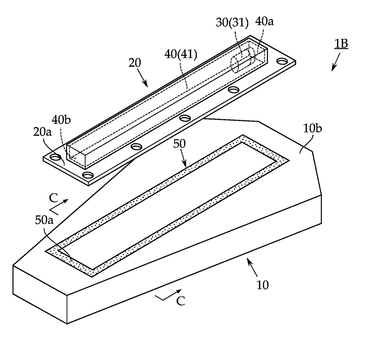
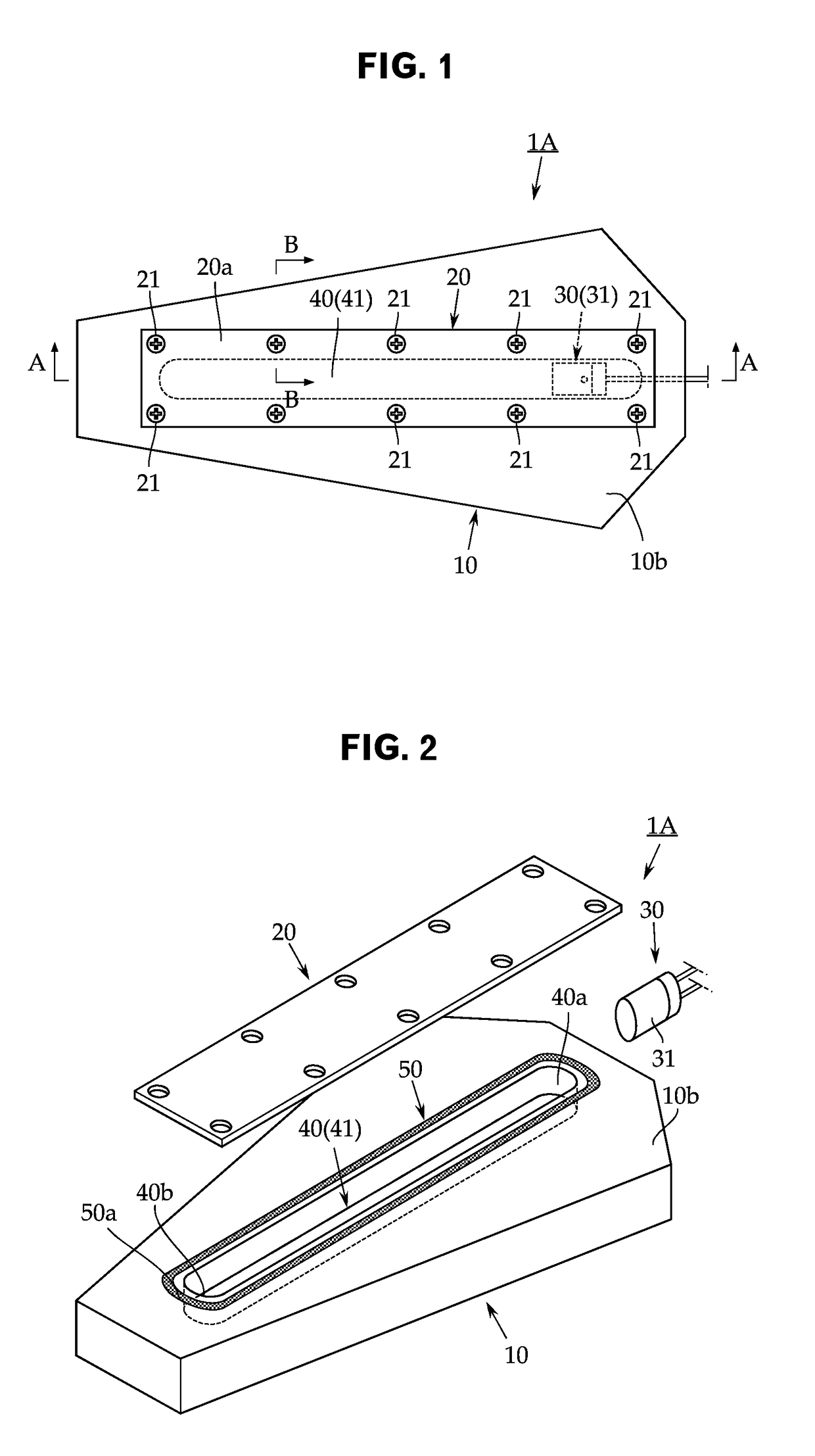
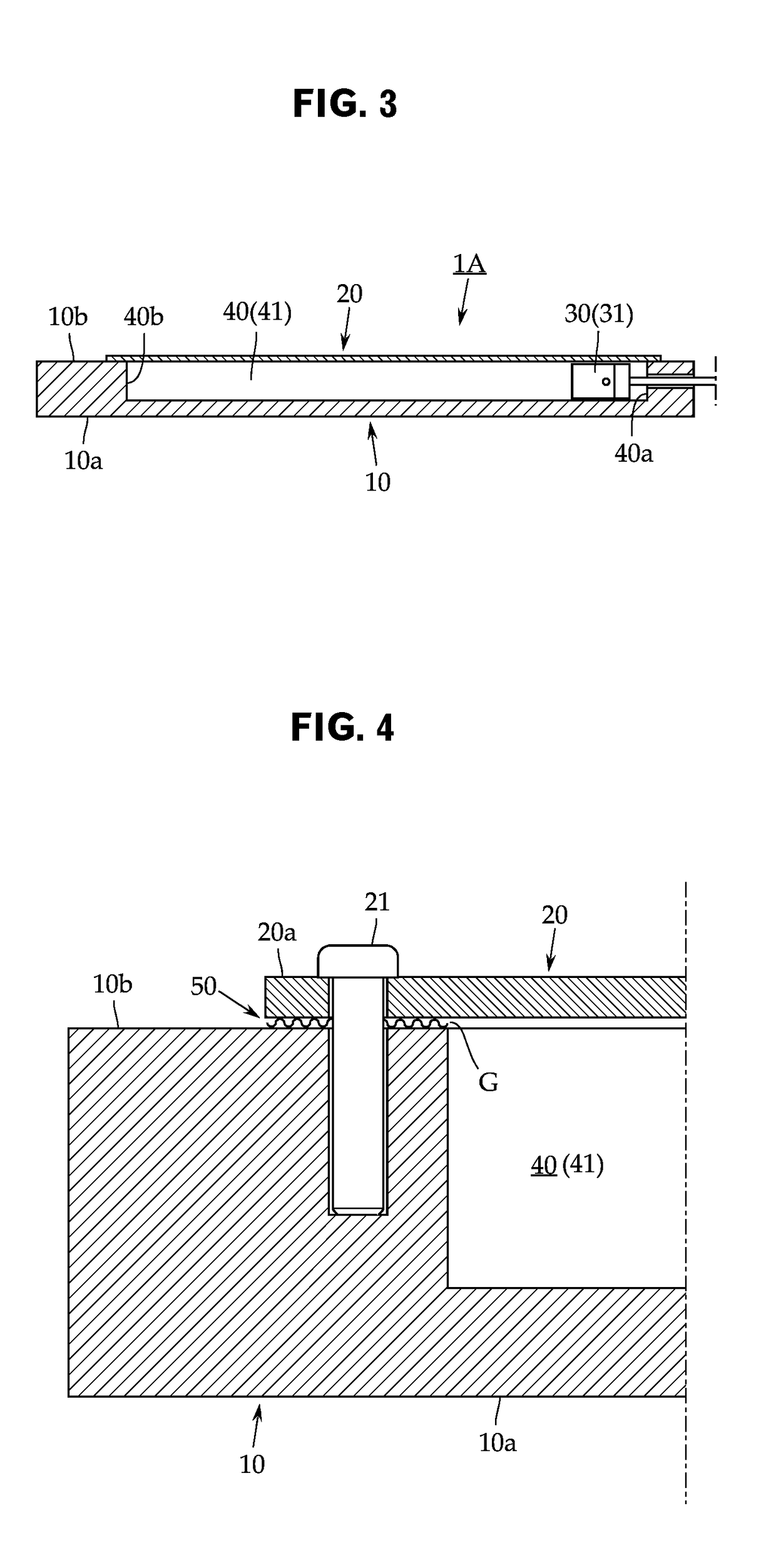
[0025]First, a boundary microphone 1A according to the first embodiment is described with FIG. 1 to FIG. 5. The boundary microphone 1A includes a base plate 10, a cover plate 20 and a microphone unit 30 for a basic configuration.

[0026]The base plate 10 is intended to be stably placed, for example, on a table, a floor surface or the like in a conference room and is composed of a metal or hard synthetic resin material that has considerable weight, and its bottom face 10a is formed to be flat. Not shown in the figures, rubber pads may be attached onto the bottom face 10a, for example, at its four corners.

[0027]Since the boundary microphone 1A is a narrow directional boundary microphone, a unidirectional microphone unit 31 having an acoustic tube 40 is used for the microphone unit 30. In the first embodiment, the acoustic tube 40 ...


PUM


Abstract

There is provided a boundary microphone inside which a unidirectional microphone unit is contained, the microphone including: a base plate; and a cover plate attached onto an upper face side thereof, wherein a thin and long tubular groove acting as an acoustic tube for making unidirectivity of the microphone unit a narrow directivity is formed on the base plate side, and therein, the microphone unit is contained. In order to prevent liquid from entering the tubular groove from the outside, between a peripheral edge part of the cover plate and the upper face of the base plate, a spacer that is composed of a water repellent thin film material and allows an inside of the tubular groove and outside air to communicate via acoustic resistance with a thin air layer is disposed so as to enclose an entire periphery of the tubular groove.

Description

TECHNICAL FIELD[0001]The present invention relates to a flat boundary microphone placed and used on a table, a floor surface or the like, and more in detail, relates to a narrow directional boundary microphone.BACKGROUND ART[0002]A boundary microphone is also called a surface-mount microphone because of its flat entire shape and is placed and used, for example, on a table, a floor surface or the like in a conference room.[0003]For the boundary microphone, an omnidirectional microphone unit is used in many cases. There can be a case where narrow directivity is required to excellently collect sound even at a distance relatively separate from a sound source.[0004]In such a case, on the boundary microphone, a narrow directional microphone in which an acoustic tube is attached to a unidirectional microphone unit is mounted. In this type of narrow directional microphone having an acoustic tube, a thin and long slit-shaped opening (side opening for sound wave) is provided on the tube wall ...

Claims


Application Information

Patent Timeline
Patent Type & Authority Applications(United States)
IPC IPC(8): H04R1/34H04R1/08H04R1/44
CPCH04R1/342H04R1/086H04R1/44H04R31/006H04R2201/029
Inventor AKINO, HIROSHI
Owner AUDIO-TECHNICA
Why Eureka
Try Eureka