Microphone array device, conference system including microphone array device and method of controlling a microphone array device

a microphone array and array device technology, applied in the field of microphone array devices, can solve problems such as disturbing echoing effects, and achieve the effect of facilitating and much faster echo cancellation

Active Publication Date: 2021-01-05
SENNHEISER ELECTRONICS GMBH & CO KG
View PDF3 Cites 2 Cited by
  • Summary
  • Abstract
  • Description
  • Claims
  • Application Information

AI Technical Summary

Benefits of technology

[0008]In an embodiment, the signal received at the mode input is a signal that indicates whether or not a remote participant is talking. While the mode input signal indicates that the remote participant is talking, the processing unit switches to the default beam mode. An advantage of this mode is that an echo cancellation may become easier and much quicker, since an AEC unit may use a default echo compensation mode that is independent from the microphone array's dynamic audio beam. Thus, the AEC unit may use a default echo compensation mode that is statically or dynamically adapted to the directivity pattern of the default beam mode. Another advantage is that the microphone array device continues to acquire the voices of participants at least in a default area of the conference room, regardless where in the default area they are located, due to the broad directivity pattern. The default area may cover the complete conference room or any portion thereof. Thus, it remains possible for a local participant to interrupt a currently talking remote participant, since the microphone array is not switched off while the remote participant is talking. Generally, it is to be noted that the invention is advantageous for any echo cancellation at least for microphone arrays that use dynamic beam forming or switch beam directions too quickly for the AEC to follow. The invention can be used independent from the replayed signal, which may be e.g. a talking remote participant or any other audio signal.

Problems solved by technology

However, since the microphones 1100 may detect the loudspeakers 1200 replaying the remote participants' voice as a sound source, a disturbing echoing effect may occur.
However, the direction of the steerable beam has an impact on the acoustic transmission path.

Method used


Image

  • Microphone array device, conference system including microphone array device and method of controlling a microphone array device
  • Microphone array device, conference system including microphone array device and method of controlling a microphone array device
  • Microphone array device, conference system including microphone array device and method of controlling a microphone array device

Examples


Embodiment Construction

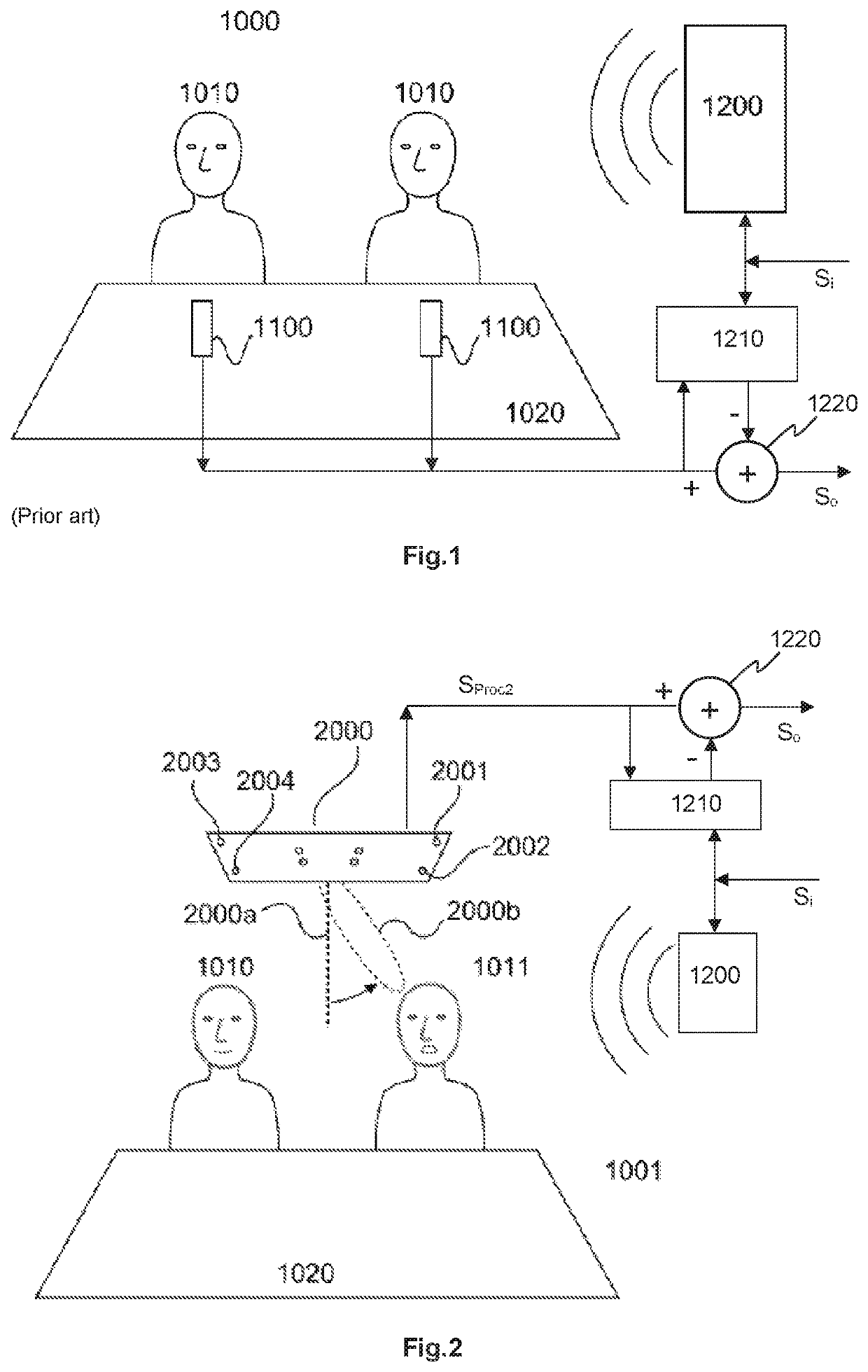
[0019]FIG. 2 shows a known conference system as disclosed in U.S. Pat. No. 9,894,434 B2, enhanced by a hypothetic acoustic echo cancelling (AEC) unit 1210. As described above, the AEC unit 1210 analyzes the audio signal SProc2 that is output by the microphone array 2000 and that is based on signals coming from the microphone capsules 2001-2004. The AEC unit 1200 models, by an adaptive filter, an acoustic transmission path from an external input audio signal Si to be replayed via the loudspeaker 1200, over-the-air transmission and microphone capsules 2001-2004. The microphone array 2000 uses dynamic beam forming to focus a beam 2000b on a talking participant 1011. The output signal of the AEC unit 1210 is subtracted 1220 from the output signal SProc2 of the microphone array 2000 in order to compensate for echo signals. However, as also mentioned above, the adaptive filter in the AEC unit 1210 depends on the direction of the beam 2000b, which may vary very quickly, e.g. within less th...


PUM


Abstract

A microphone array device including microphone capsules and at least one processing unit configured to receive output signals of the microphone capsules, dynamically steer an audio beam based on the received output signal of the microphone capsules, and generate and provide an audio output signal based on the received output signal of the microphone capsules. The processing unit is configured to operate in a dynamic beam mode where at least one focused audio beam is formed that points towards a detected audio source and in a default beam mode where a broader audio beam is formed that covers substantially a default detection area. The microphone array may be incorporated into a conference system.

Description

FIELD OF THE INVENTION[0001]The present invention relates to a microphone array device, a conference system including the microphone array device and a method of controlling a microphone array device.BACKGROUND[0002]It is noted that citation or identification of any document in this application is not an admission that such document is available as prior art to the present invention.[0003]In a conference system, the speech signal of one or more participants who are typically located in a conference room must be acquired such that it can be transmitted to remote participants or for local replay, recording or other processing. Various microphone arrangements for acquiring voice signals of the participants in the conference room are known. FIG. 1 shows participants 1010 in a conference room 1000 with microphones 1100 arranged on a table 1020. On the other hand, voice signals from remote participants are received and usually replayed in the conference room via loudspeakers 1200. However...

Claims


Application Information

Patent Timeline
Patent Type & Authority Patents(United States)
IPC IPC(8): H04R3/00G10L21/0232H04R1/40G10L21/0208
CPCH04R3/005G10L21/0232H04R1/406G10L2021/02082G10L2021/02166H04R2201/401H04R2430/20
Inventor RASUMOW, EUGENRIECK, SEBASTIANLOGEMANN, FABIANWERNER, JENS
Owner SENNHEISER ELECTRONICS GMBH & CO KG
Why Eureka
Try Eureka