
Speaker

a speaker and full-range technology, applied in the field of full-range speakers, can solve the problems of poor sound quality, inability to improve the directivity in a direction away from the speaker axis, and the inability of a single speaker to reproduce low to high frequencies with excellent sound quality, etc., to achieve excellent high frequency response, increase mass and mechanical resistance, and reduce effective vibration area

Inactive Publication Date: 2012-03-13
PANASONIC CORP
View PDF29 Cites 1 Cited by
  • Summary
  • Abstract
  • Description
  • Claims
  • Application Information

AI Technical Summary

Benefits of technology

"The present invention provides a speaker with excellent high frequency response and mid-high frequency response. The speaker includes a diaphragm with a corrugation and a damping member attached to the diaphragm. The damping member extends the overlap of the speaker edge with the diaphragm and increases the mass and mechanical resistance in the outer peripheral part of the diaphragm to suppress vibration transmission at high frequencies. This results in a broader reproducible frequency range and improved directivity at high frequencies. The damping member is integrated with the speaker edge to suppress an increase in cost."

Problems solved by technology

In general, however, it is difficult for a single speaker to reproduce low to high frequencies with excellent sound quality, and in particular to reproduce high frequencies with an excellent response.
However, the directivity in a direction away from the axis of the speaker cannot be improved.
However, high frequency sounds radiated from the diaphragm and high frequency sounds radiated from the sub-cone interfere with each other to cause the degradation of sound quality.

Method used


Image

  • Speaker
  • Speaker
  • Speaker

Examples


embodiment 1

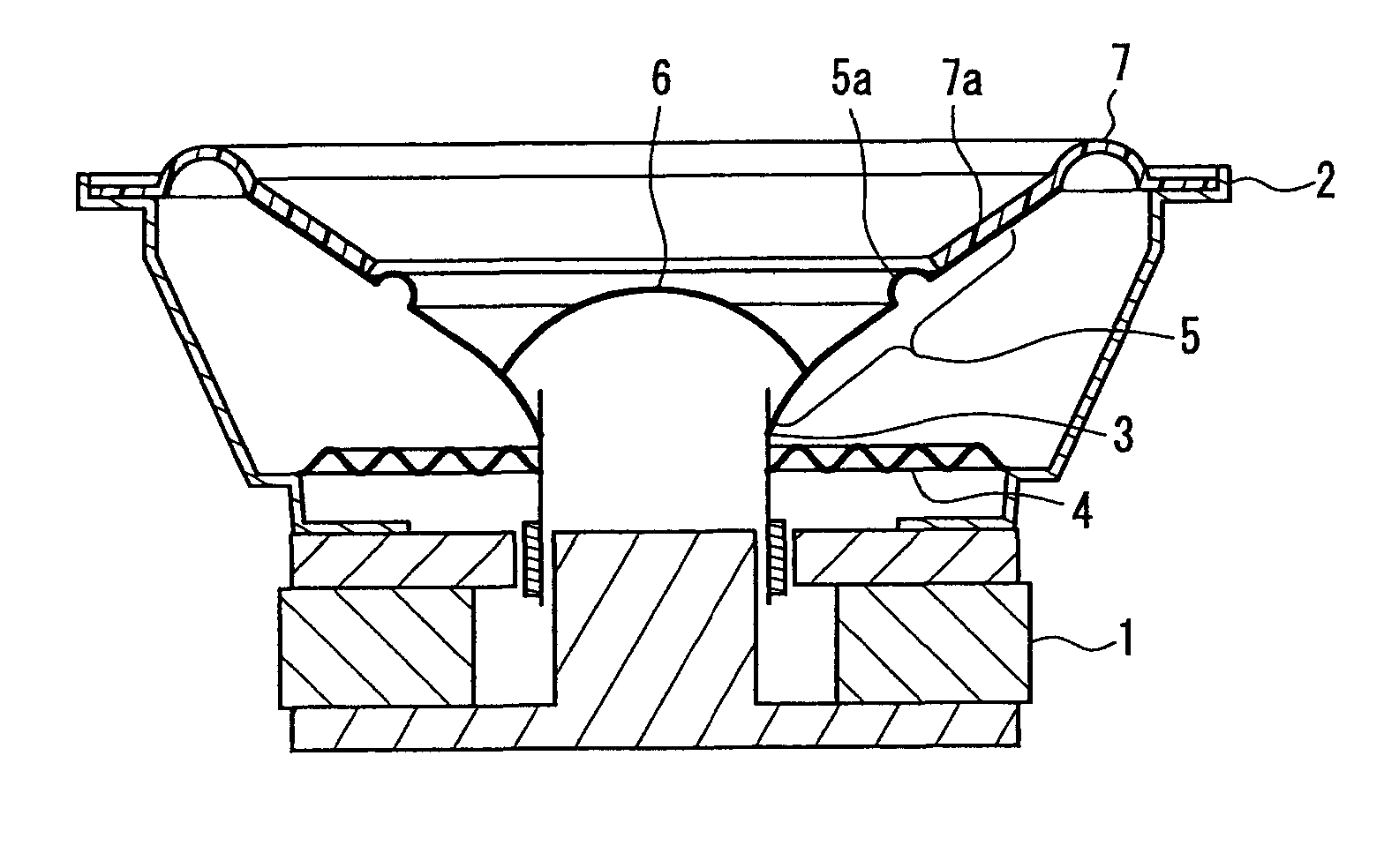
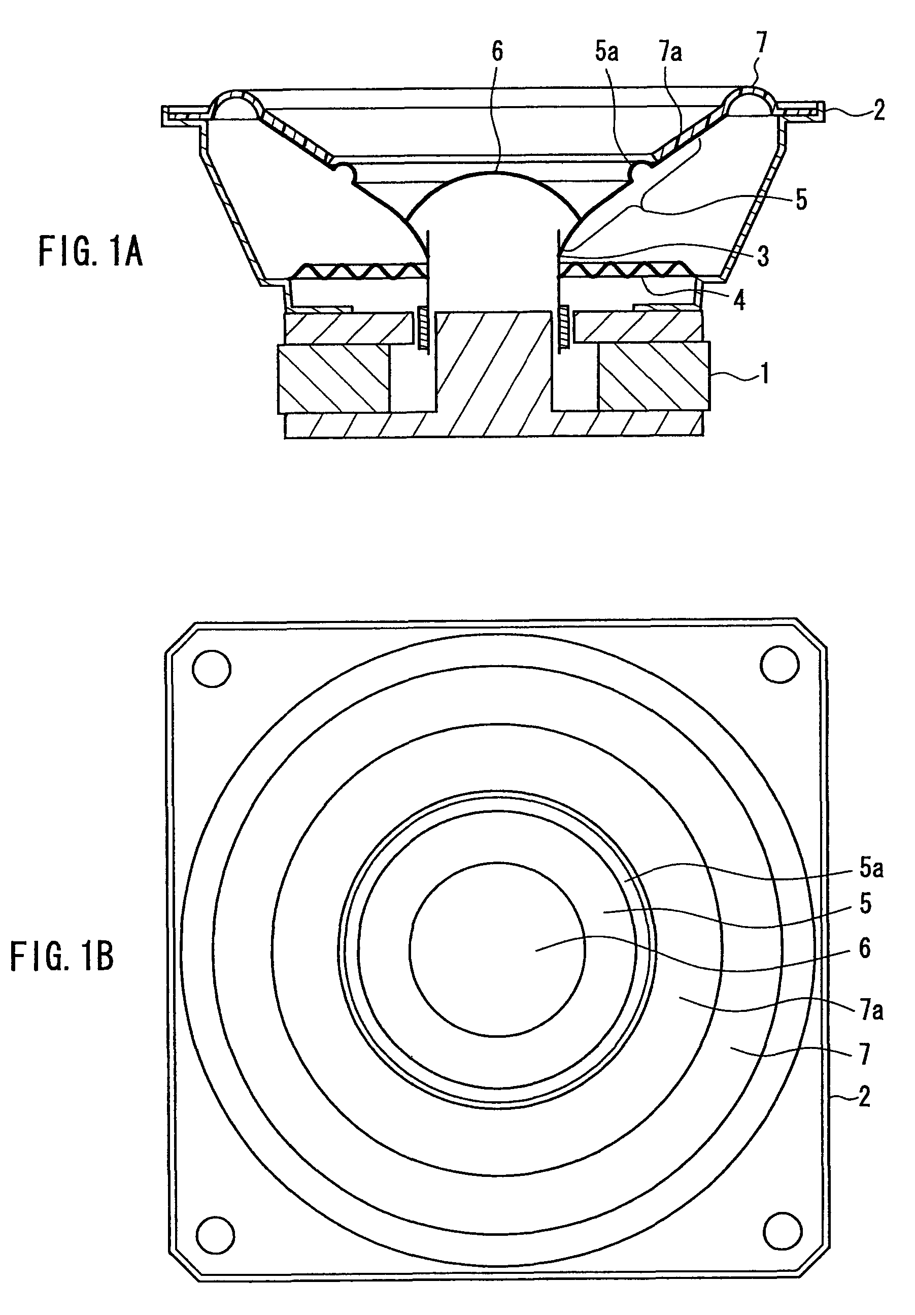
[0032]First, the configuration of a speaker according to a first embodiment of the present invention will be described with reference to FIG. 1. FIGS. 1A and 1B are diagrams showing the configuration of the speaker according to the first embodiment of the present invention. FIG. 1A shows the cross section of the speaker and FIG. 1B shows the front appearance of the speaker.

[0033]In FIG. 1, a field magnet 1, a damper 4, and a speaker edge 7 are attached to a frame 2, and a voice coil 3 is supported by the damper 4. A diaphragm 5 has a cone shape, and its inner periphery is coupled to the voice coil 3 and its outer periphery is supported by the speaker edge 7. A dust cap 6 is attached to the vicinity of an inner peripheral part of the diaphragm 5.

[0034]A corrugation 5a is provided at the intermediate position of the diaphragm 5. A damping portion 7a that is formed as a part of the speaker edge 7 is attached to an outer peripheral part of the diaphragm 5 outside the vicinity of the out...

embodiment 2

[0066]Next, a speaker according to a second embodiment of the present invention will be described with reference to FIG. 6. FIG. 6 is a cross sectional view showing the main portion of the configuration of the speaker according to the second embodiment. In FIG. 6, a frame 12, a voice coil, a damper 14, and a dust cap 16 are identical to those in the first embodiment, and the description will not be repeated.

[0067]The second embodiment is different from the first embodiment in a diaphragm 15, a corrugation 15a, a speaker edge 17, and a damping potion 17a for the diaphragm 15. The material of the diaphragm 15 is pulp having a thickness of about 0.3 mm. Though the inner and outer diameters of the diaphragm 15 are the same as those in the first embodiment, the corrugation 15a has a stepped shape. The diameter of the inner periphery of the corrugation 15a is 36 mm, and the diameter of the outer periphery is 38 mm, and the height of the step is 0.7 mm.

[0068]The material of the speaker edg...

embodiment 3

[0071]FIG. 7 shows the configuration of a speaker according to a third embodiment of the present invention. In FIG. 7, the speaker has a diameter of 6.5 cm and is a dome-shaped full-range speaker. The configurations of a field magnet 21, a frame 22, a voice coil 23, and a damper 24 are similar to those in the first embodiment, and the description will not be repeated.

[0072]In the third embodiment, the material of a diaphragm 25 is aluminum having a thickness of 0.1 mm. The diaphragm 25 has an outer diameter of 46 mm and has a dome shape. The cross section of a corrugation 25a is substantially in the form of a ⅓ concave circular arc, and the radius of curvature of the cross section is about 0.7 mm. The diameter of the outer periphery of the corrugation 25a is 35 mm, and the diameter of the inner periphery is 33 mm.

[0073]The material of a speaker edge 27 is a foam rubber having a thickness of 0.5 mm. The diameter of the outer periphery of a rounded portion of the speaker edge 27 is 58...


PUM


Abstract

A speaker of the present invention includes the following: a diaphragm that includes an inner periphery coupled to a voice coil, and a corrugation provided at the intermediate position between the inner periphery and an outer periphery; a speaker edge for supporting the outer periphery of the diaphragm; and a damping member attached to an outer peripheral part of the diaphragm outside the vicinity of an outer periphery of the corrugation. The effective vibration area of an inner peripheral part of the diaphragm inside an inner periphery of the corrugation is substantially half or less of the total effective vibration area. The damping member is configured as a damping portion by extending an overlap portion of the speaker edge overlapping with the diaphragm to the vicinity of the outer periphery of the corrugation. This configuration can suppress the vibration transmission at high frequencies to the outer peripheral part of the diaphragm outside the corrugation, allows only the inner peripheral part of the diaphragm inside the corrugation to mainly vibrate at high frequencies, and also can suppress a resonance in the outer peripheral part of the diaphragm outside the corrugation. Thus, the speaker can have both an excellent high frequency response and an excellent mid-high frequency response.

Description

BACKGROUND OF THE INVENTION[0001]1. Field of the Invention[0002]The present invention relates mainly to a full-range speaker used widely in stereos, multi-channel sound reproduction devices, radios, and televisions.[0003]2. Description of Related Art[0004]In recent years, many speakers have been installed in homes as multi-channel home theater reproduction devices or the like become widely available. For this reason, further miniaturization and cost reduction of the speakers have been required. Therefore, instead of using the speakers in a multi-way configuration, it is desired that a single speaker be capable of reproducing low to high frequencies with high sound quality.[0005]In general, however, it is difficult for a single speaker to reproduce low to high frequencies with excellent sound quality, and in particular to reproduce high frequencies with an excellent response. This is because the diameter of a speaker cannot be too small in order to reproduce the low frequencies to so...

Claims


Application Information

Patent Timeline
Patent Type & Authority Patents(United States)
IPC IPC(8): H04R1/00H04R11/02H04R9/06H04R7/00H04R25/00
CPCH04R1/24H04R7/14H04R7/18H04R7/122H04R7/26
Inventor TANAKA, SHOJITSUTSUMI, HIROKOYUASA, TAKAFUMI
Owner PANASONIC CORP
Learn More