Antenna and electronic apparatus

an electronic apparatus and antenna technology, applied in the direction of resonant antennas, elongated active elements, instruments, etc., can solve the problems of difficult manufacture, narrow frequency band in which the required circularly polarized wave can be generated, and the maximum sensibility direction of the antenna in the direction of the satellite, etc., to achieve wide circularly polarized wave directivity, wide frequency band, and high radiation efficiency

Active Publication Date: 2018-12-11
SEIKO EPSON CORP
View PDF35 Cites 0 Cited by
  • Summary
  • Abstract
  • Description
  • Claims
  • Application Information

AI Technical Summary

Benefits of technology

[0014]An advantage of some aspects of the invention is to provide a circularly polarized wave antenna which is small and has a wide circularly polarized wave directivity, a wide frequency band and a high radiation efficiency, a communication apparatus using this, and an electronic apparatus.

Problems solved by technology

Besides, in an apparatus, such as a GPS equipment, which is mounted on a person or an animal and is used, it is difficult to always keep the maximum sensibility direction of the antenna in the direction toward the satellite.
The patch antenna has defects that as the operation frequency becomes high, the perturbation element becomes small, and the manufacture becomes difficult, and further, the frequency band in which the required circularly polarized wave can be generated is very narrow.
Thus, in the patch antenna, it is difficult to obtain the wide directional pattern of the circularly polarized wave.
Further, since the patch antenna uses a dielectric body, the loss of the dielectric body cannot be avoided.
Since the spiral antenna or the curl antenna is a travelling-wave type antenna, the antenna is generally large, and although the band is wide, the directivity is sharp, and application to a portable equipment is difficult.
Hitherto, there is no antenna satisfying all these requests.

Method used


Image

  • Antenna and electronic apparatus
  • Antenna and electronic apparatus
  • Antenna and electronic apparatus

Examples


first embodiment

A. First Embodiment

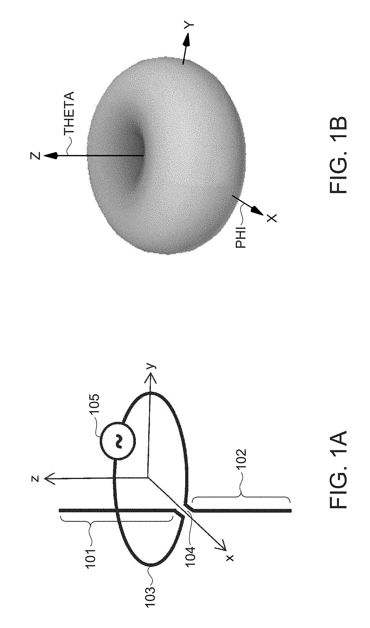
[0050]FIG. 1A is a perspective view showing an outer appearance of an antenna of a first embodiment, and FIG. 1B is a view showing a directivity characteristic thereof. The antenna of the embodiment includes a loop-shaped loop element (magnetic current element) 103, and a first and a second linear element (electric current element) 101 and 102. These elements can be easily constructed by using a wire such as a copper wire or a pipe. The elements may be formed by bonding, etching, printing or the like of a conductive foil to a suitably shaped base. The loop element 103 has a gap 104, one end of the gap 104 is connected to one end of the first linear element 101, and the other end of the gap 104 is connected to one end of the second linear element 102.

[0051]Reference numeral 105 denotes a power supply source (power supply unit). In the embodiment, another gap is provided on the opposite side of the gap 104 of the loop element 103 and power is supplied. Although powe...

modified example 1

[0082]The radiation impedance of the antenna of the first embodiment is very low. As shown in FIG. 4A, a stub 401 is added so that the radiation impedance can be adjusted. Incidentally, for simplification of the following description, an already-described portion is denoted by the same reference numeral and its description is omitted.

modified example 2

[0083]In FIG. 4B, a power supply source 105 is located in a gap 104 of a loop element 103. This may be considered such that the stub connection point of FIG. 4A is moved to the gap 104. In this case, the loop element 103 and the linear elements 101 and 102 are connected in parallel when seen from the power supply side, values of currents flowing to the respective elements are easily adjusted and the frequency band can also be widened.


PUM


Abstract

An antenna includes a magnetic current element which is an element to constitute a loop and generates a magnetic current vector having a component perpendicular to a loop plane, and an electric current element to generate an electric current vector having a component parallel to the magnetic current vector.

Description

CROSS REFERENCES TO RELATED APPLICATIONS[0001]This application claims priority to Japanese Patent Application No. 2013-206160 filed on Oct. 1, 2013, the entirety of which is hereby incorporated by reference.BACKGROUND[0002]1. Technical Field[0003]The present invention relates to an antenna and an electronic apparatus including the antenna, and particularly to a mobile or portable electronic apparatus.[0004]2. Related Art[0005]For example, in a satellite mobile phone or a navigation apparatus using GPS (Global Positioning System), wireless communication using a circularly polarized wave is performed. Although the circularly polarized wave can be received by a linearly polarized wave antenna, since the gain is halved, it is preferable to use a circularly polarized wave antenna. Besides, in an apparatus, such as a GPS equipment, which is mounted on a person or an animal and is used, it is difficult to always keep the maximum sensibility direction of the antenna in the direction toward ...

Claims


Application Information

Patent Timeline
Patent Type & Authority Patents(United States)
IPC IPC(8): H01Q7/00G01S5/02H01Q9/30H01Q9/16H01Q1/27
CPCH01Q7/00G01S5/02H01Q9/30H01Q9/16H01Q1/273
Inventor IKEDA, MASAYUKIAIZAWA, TADASHI
Owner SEIKO EPSON CORP
Why Eureka
Try Eureka