Laryngoscope Handle

Inactive Publication Date: 2015-02-19
OBP MEDICAL
View PDF2 Cites 8 Cited by
  • Summary
  • Abstract
  • Description
  • Claims
  • Application Information

AI Technical Summary

Benefits of technology

[0017]Accordingly, the present invention allows fluid generated during medical procedures to flow into the areas away from where the operator's hand co

Problems solved by technology

These handles often become contaminated with blood, vomit, or other fluids from the patient or from the environment.
These fluids will reduce the contact resistance between the operator's hand and the laryngoscope, and make the laryngoscope difficult to hold during

Method used


Image

  • Laryngoscope Handle
  • Laryngoscope Handle
  • Laryngoscope Handle

Examples


Embodiment Construction

[0024]Reference will now be made in detail to the present embodiments of the invention, examples of which are illustrated in the accompanying drawings. Wherever possible, the same reference numbers are used in the drawings and the description to refer to the same or like parts.

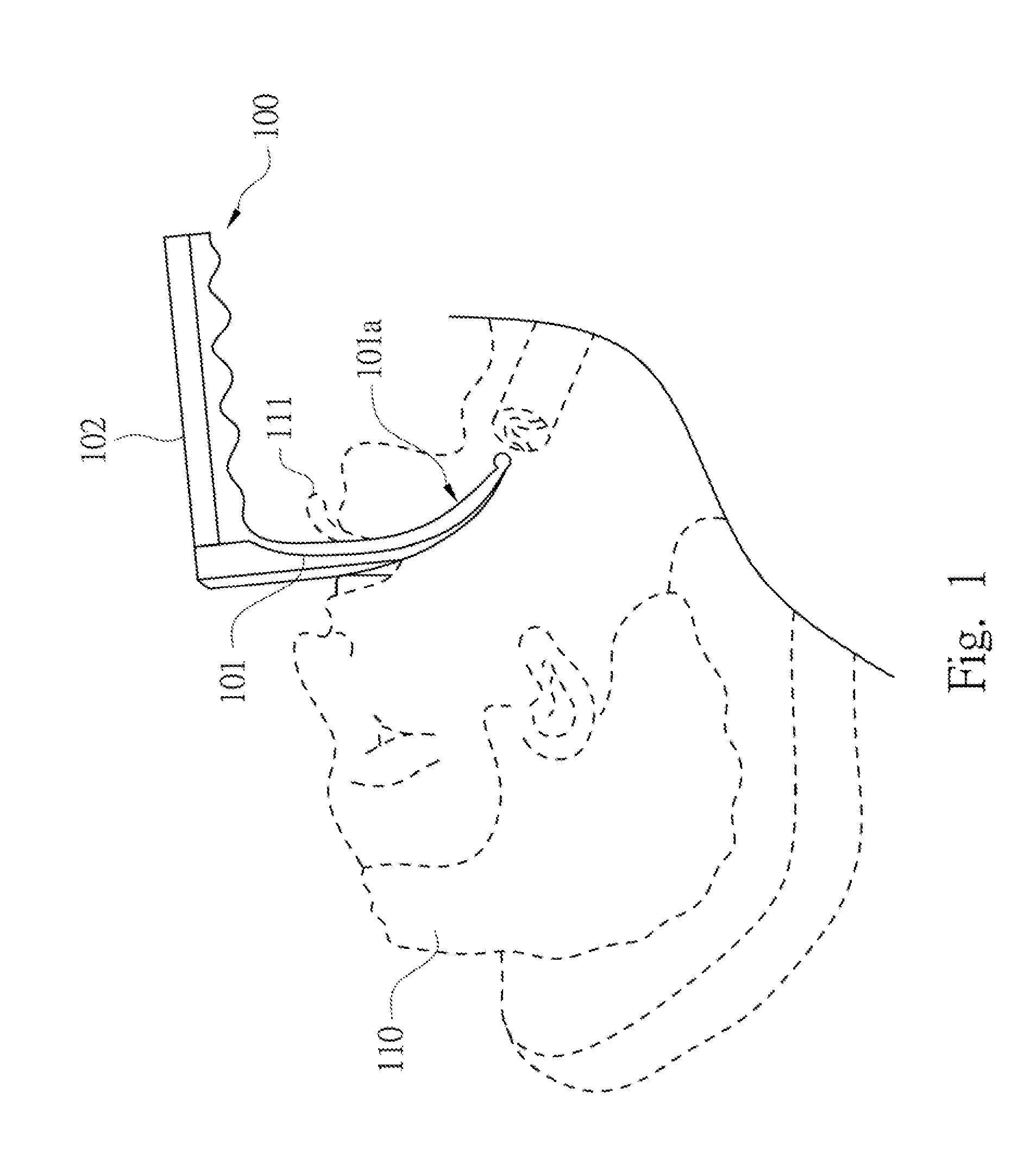
[0025]FIG. 1 is a schematic diagram of a laryngoscope being used to view a patients larynx. In FIG. 1, the laryngoscope 100 is shown placed in the mouth of a patient 110 for viewing the vocal cords adjacent the larynx. The laryngoscope 100 includes a blade portion 101 and a handle portion 102. The blade portion 101 is used to hold the patient's tongue 111 out of the way for viewing the vocal cords.

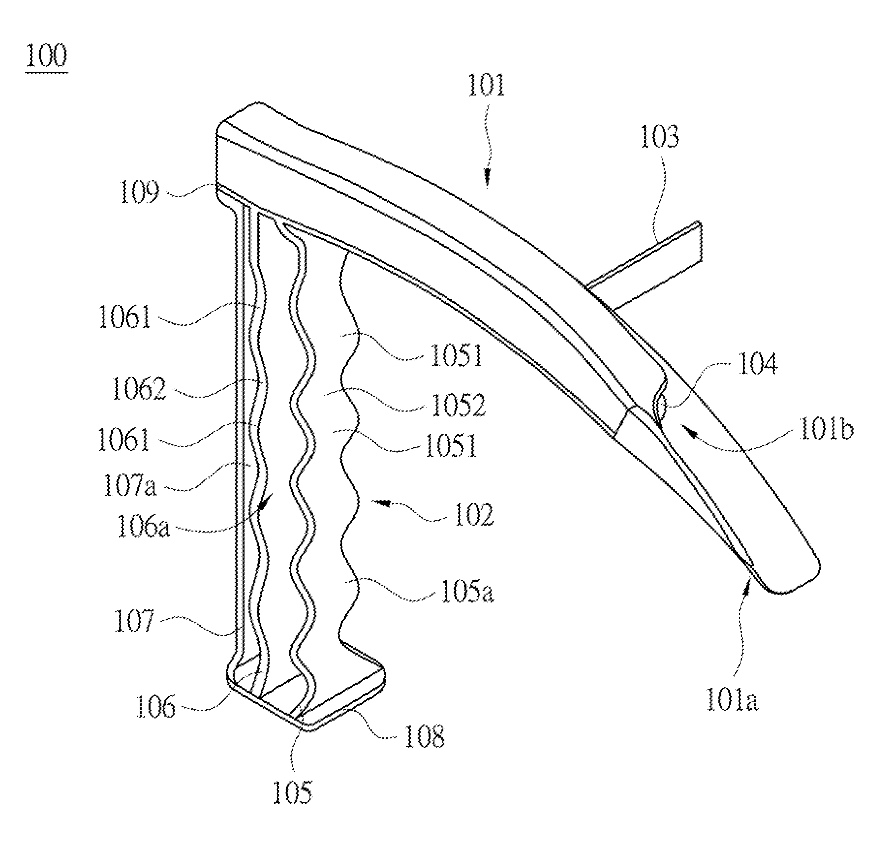
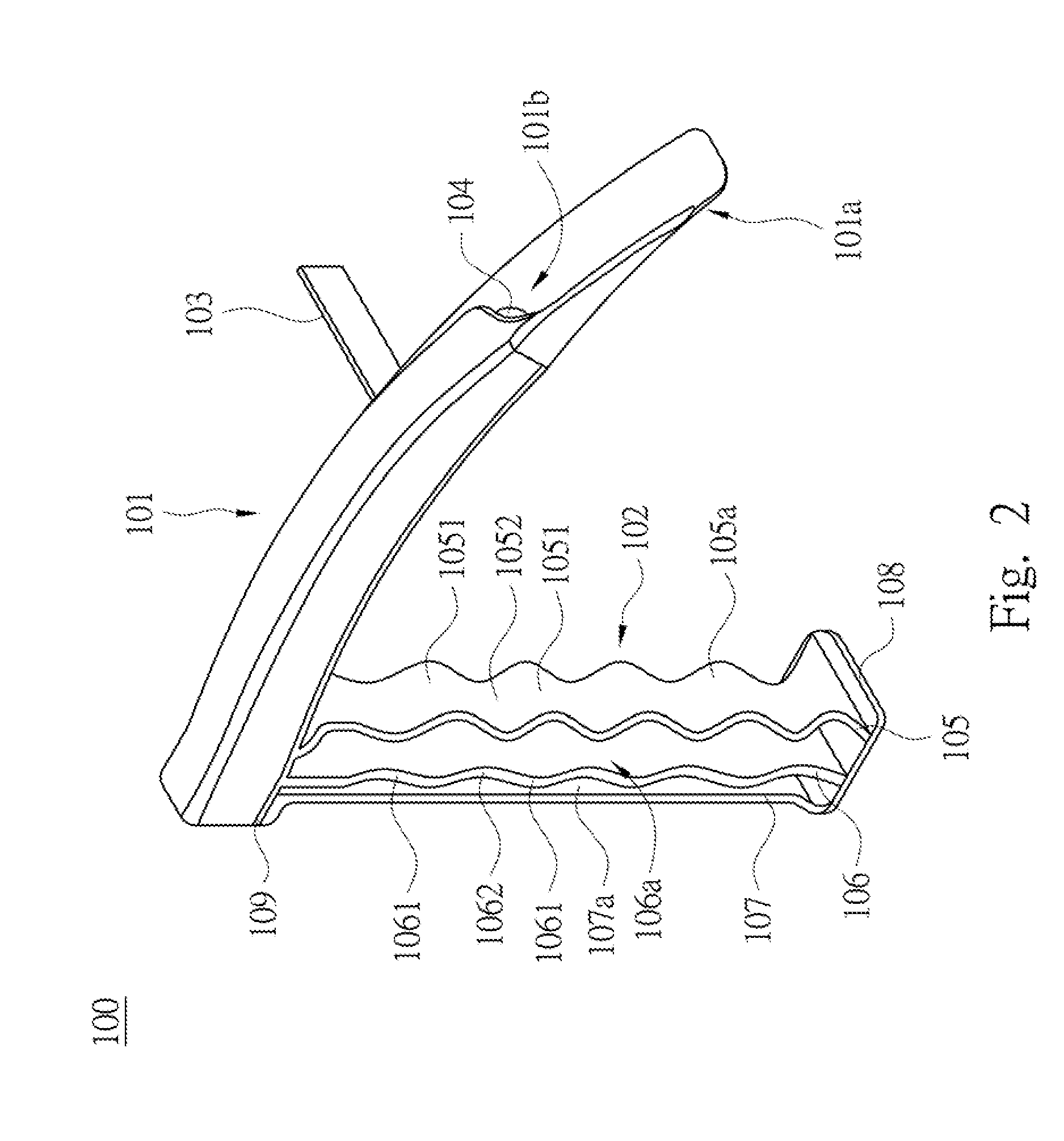
[0026]FIG. 2 is a left perspective view of the laryngoscope of FIG. 1. FIG. 3 is a right perspective view of the laryngoscope of FIG. 1. FIG. 4 is a front view of the laryngoscope of FIG. 1. FIG. 5 is a rear view of the laryngoscope of FIG. 1.

[0027]With reference to FIG. 2 to FIG. 5, the laryngoscope 100 comprises th...


PUM


Abstract

A laryngoscope comprises a blade portion and a handle portion. The handle portion comprises a plurality of grip portions, a bottom support and a top support, a bottom support and a top support. The grip portions are separated form each other. One end of each of the grip portions is mounted on the bottom support, and the other end of each of the grip portions is mounted on the top support. The blade portion is integrally formed with the top support of the handle portion and extending away from the handle portion. Each of the grip portions is formed by a two-part mold technique.

Description

BACKGROUND[0001]1. Field of Invention[0002]The present invention relates to a laryngoscope, and more particularly to a laryngoscope handle.[0003]2. Description of Related Art[0004]Health care providers perform direct laryngoscopy to either clear a patient's airway of debris, or place an endotracheal tube into a patient's trachea to assist or replace a patient's ability to oxygenate his / her system. The laryngoscope utilizes either a lighted straight or curved blade that allows visualization of the vocal cords, indicating the opening of the trachea. This lighted blade is used to keep the tongue from obstructing the medical provider's view of the vocal cords. The tip of the blade lifts the epiglottis, thereby providing a direct view into the patient's trachea, and reducing the risk of intubating the esophagus instead.[0005]Existing laryngoscopes have round handles. These handles often become contaminated with blood, vomit, or other fluids from the patient or from the environment. These...

Claims


Application Information

Patent Timeline
IPC IPC(8): A61B1/267
CPCA61B1/267A61B1/00066
Inventor SWIFT, JEFFREY RALPH
Owner OBP MEDICAL
Why Eureka
Try Eureka