Direct reduced iron water cooling cylinder device

A reduced iron, direct technology, applied in furnaces, furnace types, fluidized bed furnaces, etc., can solve the problems of increased useless water, short contact time, and large water consumption in the system, so as to reduce the degree of line of sight barrier and improve heat exchange Time, the effect of improving heat exchange efficiency

Active Publication Date: 2015-08-19
ZHONGYE-CHANGTIAN INT ENG CO LTD
View PDF8 Cites 0 Cited by
  • Summary
  • Abstract
  • Description
  • Claims
  • Application Information

AI Technical Summary

Problems solved by technology

[0007] 1. Low heat transfer efficiency: see figure 1 As shown, the water is sprayed on the outer wall of the cooling cylinder through the water spray assembly. When the cooling cylinder rotates downward, the water also flows downward along the outer wall of the cooling cylinder, and finally flows into the sump
In this case, the contact time between water and the outer wall of the high-temperature cooling cylinder is too short, resulting in low heat transfer efficiency and unable to achieve a good cooling effect
[0008] 2. The consumption of water is large: after the water is sprayed on the outer wall of the cooling cylinder through the water spray assembly, due to the rotation of the cooling cylinder and the water speed, a large part of the water falling on the wall of the cylinder will be splashed, and this part of the splashed water will not Participate in the cooling of the cylinder wall, resulting in an increase in useless water, which in turn causes a large amount of water consumption in the system
[0009] 3. Affect the surrounding environment: Since the water splashes greatly when it falls into the sump, the ground around the cooling tube will be wet and slippery during production, the operating environment is harsh, and the risk factor increases
At the same time, because the water quickly vaporizes into water vapor when it contacts the high-temperature cylinder wall, a large amount of white mist around the cooling cylinder blocks the operator's sight, resulting in frequent safety accidents

Method used


Image

  • Direct reduced iron water cooling cylinder device
  • Direct reduced iron water cooling cylinder device
  • Direct reduced iron water cooling cylinder device

Examples


Embodiment Construction

[0034] The present invention will be described in further detail below in conjunction with the accompanying drawings and specific embodiments.

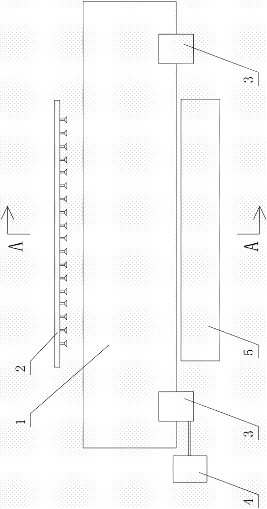
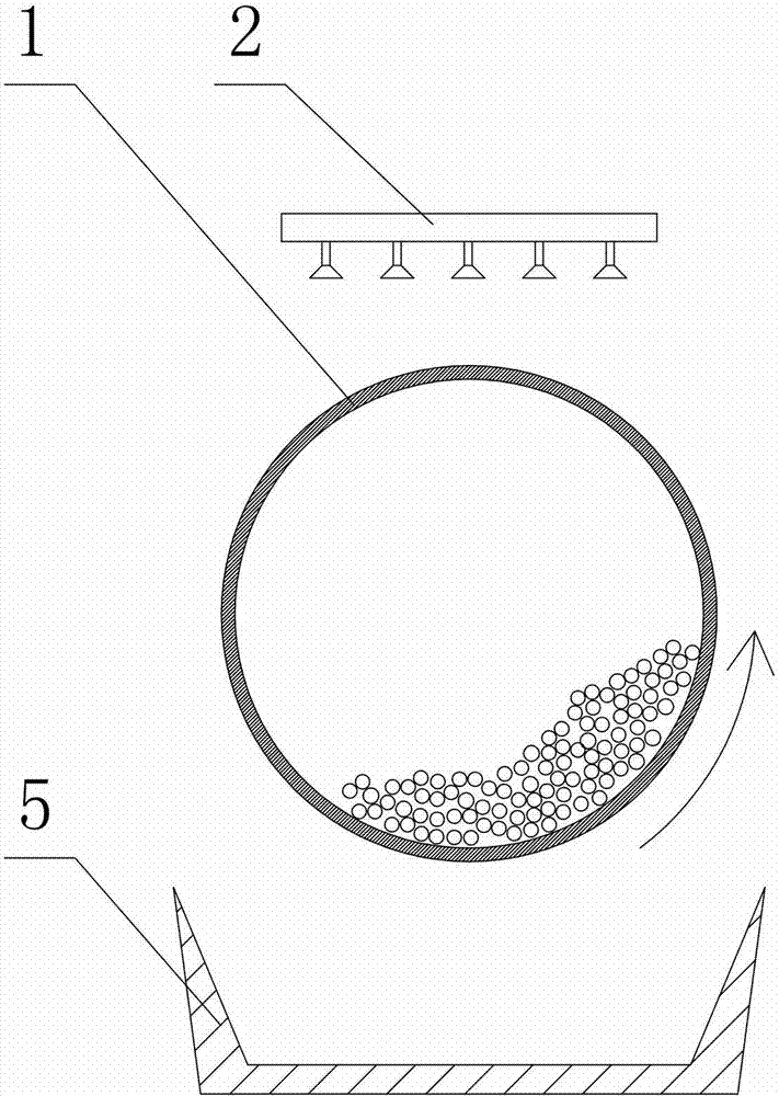
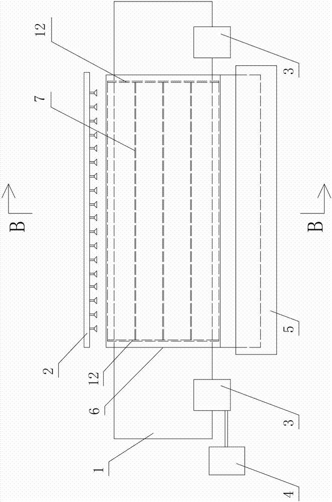
[0035] Figure 3 to Figure 5 An embodiment of the direct reduced iron water-cooled cylinder device of the present invention is shown, the device includes a cooling cylinder 1 containing materials and a water spray assembly 2, and the water spray assembly 2 includes a plurality of showers arranged above the cooling cylinder 1, Used to spray cooling water to the outer wall of the cooling cylinder 1. The cooling cylinder 1 is in the shape of a horizontal cylinder, driven to rotate by the driving assembly, so that the circumferential outer wall of the cooling cylinder 1 is cooled by cooling water; the driving assembly includes the idler mechanism 3 supported on the bottom of the cooling cylinder 1 and the idler mechanism 3 connected rotary drive mechanism 4 (such as a motor). A cover tube 6 is sleeved on the outside of the cooling tube ...


PUM


Abstract

The invention discloses a water cooling tube device for direct reduction iron. The water cooling tube device comprises a cooling tube and a spray module, wherein an outer cover tube is sleeved outside the cooling tube; a gap is reserved between the outer cover tube and the cooling tube; a water inlet in which the cooling water sprayed by the spray module enters is arranged on the lateral wall of the outer cover tube; and a water outlet is arranged at the bottom of the outer cover tube. The water cooling tube device has the advantages of being simple in structure, low in cost, high in heat exchange efficiency, less in water consumption, safe, practical and the like.

Description

technical field [0001] The invention mainly relates to the field of mining and metallurgy equipment, in particular to a direct reduced iron water cooling cylinder device. Background technique [0002] Direct Reduced Iron (DRI-Direct Reduced Iron, referred to as DRI) refers to the low-carbon porous material formed by the reduction of fine iron powder or iron oxide in a furnace at low temperature. Its chemical composition is stable and its impurity content is low. Unlike sinter and oxidized pellets that are fed into the blast furnace for ironmaking, most of the direct reduction iron ore is used as raw material for electric furnace and converter steelmaking, which can increase the uniformity of the steel and improve the physical properties of the steel, thereby achieving production The purpose of high-quality steel. Direct reduced iron is not only a substitute for high-quality steel scrap, but also an indispensable high-grade raw material for the production of high-quality ste...

Claims


Application Information

Patent Timeline
Patent Type & Authority Patents(China)
IPC IPC(8): C21B13/00
Inventor 周浩宇储太山
Owner ZHONGYE-CHANGTIAN INT ENG CO LTD
Why Eureka
Try Eureka