Conveyor system

a conveyor system and conveying device technology, applied in the direction of conveying devices, underground transportation, earthwork drilling and mining, etc., can solve the problems of inconvenient continuous flow material handling systems, high maintenance costs, and many personnel injuries and deaths

Active Publication Date: 2015-03-19
DW TECH
View PDF9 Cites 14 Cited by
  • Summary
  • Abstract
  • Description
  • Claims
  • Application Information

AI Technical Summary

Problems solved by technology

They also contribute significantly to capital and maintenance costs, as well as causing numerous personnel injuries and deaths.
Because these cut-throughs are developed at 90 degrees to the roads, conventional continuous flow materials handling systems are not suitable.

Method used


Image

  • Conveyor system
  • Conveyor system
  • Conveyor system

Examples


Embodiment Construction

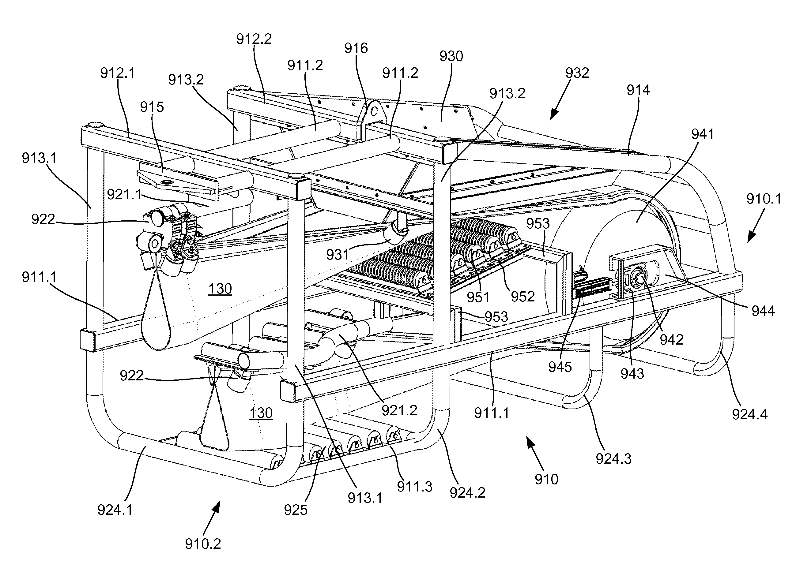
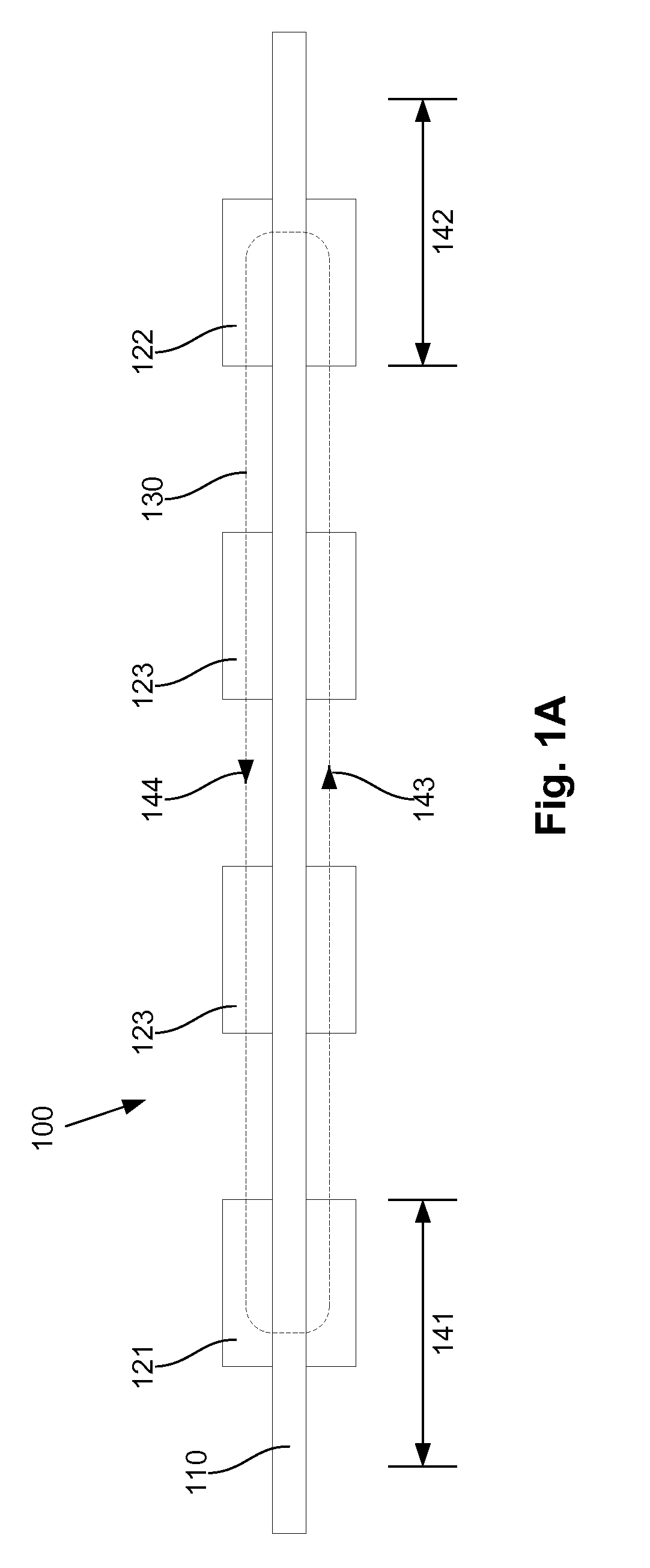
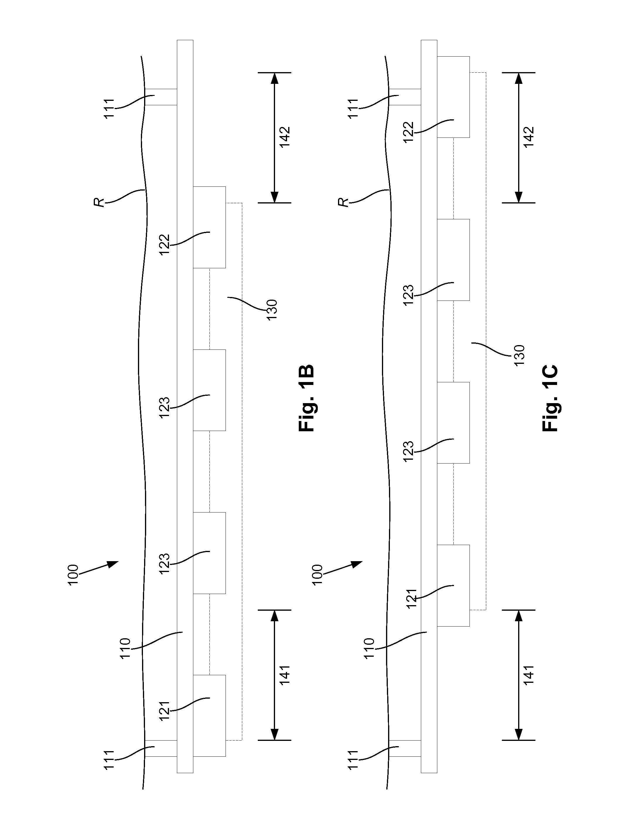
[0070]An example of a conveyor system will now be described with reference to FIGS. 1A to 1F.

[0071]In this example, the conveyor system 100 includes a track 110 extending between a loading region 141 and a discharge region 142. The conveyor system 100 includes an endless belt 130, bendable into a tubular shape and having thickened edges to allow the belt to be supported by a number of belt rollers, which are in turn mounted on a number of carriages 121, 122, 123 that are moveably mounted to the track 110.

[0072]The carriages typically include a loading carriage 121 which is movable within the loading region 141 to allow material to be loaded onto the belt, a discharge carriage 122 movable within the discharge region 142, to allow material to be discharged from the belt, and one or more intermediate carriages 123 positioned between the loading and discharge carriages 121, 122, to support the belt along a transport and return path indicated by the arrows 143, 144.

[0073]By movably mount...


PUM


Abstract

A conveyor system including a track extending between a loading region and a discharge region, an endless belt bendable into a tubular shape, the endless belt having thickened edges, a number of carriages moveably mounted to the track, the carriages including belt rollers for engaging the edges of the belt to thereby support the belt, a loading carriage for allowing material to be loaded onto the belt, the loading station being moveable at least within the loading region, a discharge carriage for allowing material to be discharged from the belt, the discharge station being moveable at least within the discharge region and a number of intermediate carriages positioned between the loading and discharge carriages for supporting the belt along transport and return paths with the tubular shape.

Description

BACKGROUND OF THE INVENTION[0001]The present invention relates to a conveyor system, and in one particular example, to a conveyor system for use in mining.DESCRIPTION OF THE PRIOR ART[0002]The reference in this specification to any prior publication (or information derived from it), or to any matter which is known, is not, and should not be taken as an acknowledgment or admission or any form of suggestion that the prior publication (or information derived from it) or known matter forms part of the common general knowledge in the field of endeavour to which this specification relates.[0003]The introduction of Longwall Mining to the Australian Coal Industry in the early eighties and the acceptance of this technology by mining companies, resulted in more efficient and cost effective methods of production and plant utilisation. This change within the Industry has brought about a broadening of market opportunities not only for the mining companies but also for plant / equipment suppliers.[...

Claims


Application Information

Patent Timeline
Patent Type & Authority Applications(United States)
IPC IPC(8): E21F13/08B65G23/44B65G15/60B65G15/08B65G21/14
CPCE21F13/08B65G15/08B65G23/44B65G15/60B65G21/14B65G21/10
Inventor WHELAN, DARREN JOHN
Owner DW TECH
Why Eureka
Try Eureka