Blood pump apparatus

Active Publication Date: 2015-03-19
TC1 LLC
View PDF4 Cites 15 Cited by
  • Summary
  • Abstract
  • Description
  • Claims
  • Application Information

AI Technical Summary

Benefits of technology

[0006]The inventor here has discovered that where a magnetic material is provided in the housing on the impeller rotational torque generation section side, the impeller rotating torque generating un

Problems solved by technology

The housing in this case is required to have a certain extent of thickness for securing strength of the main body of the pump apparatus, and this struc

Method used


Image

  • Blood pump apparatus
  • Blood pump apparatus
  • Blood pump apparatus

Examples


Example

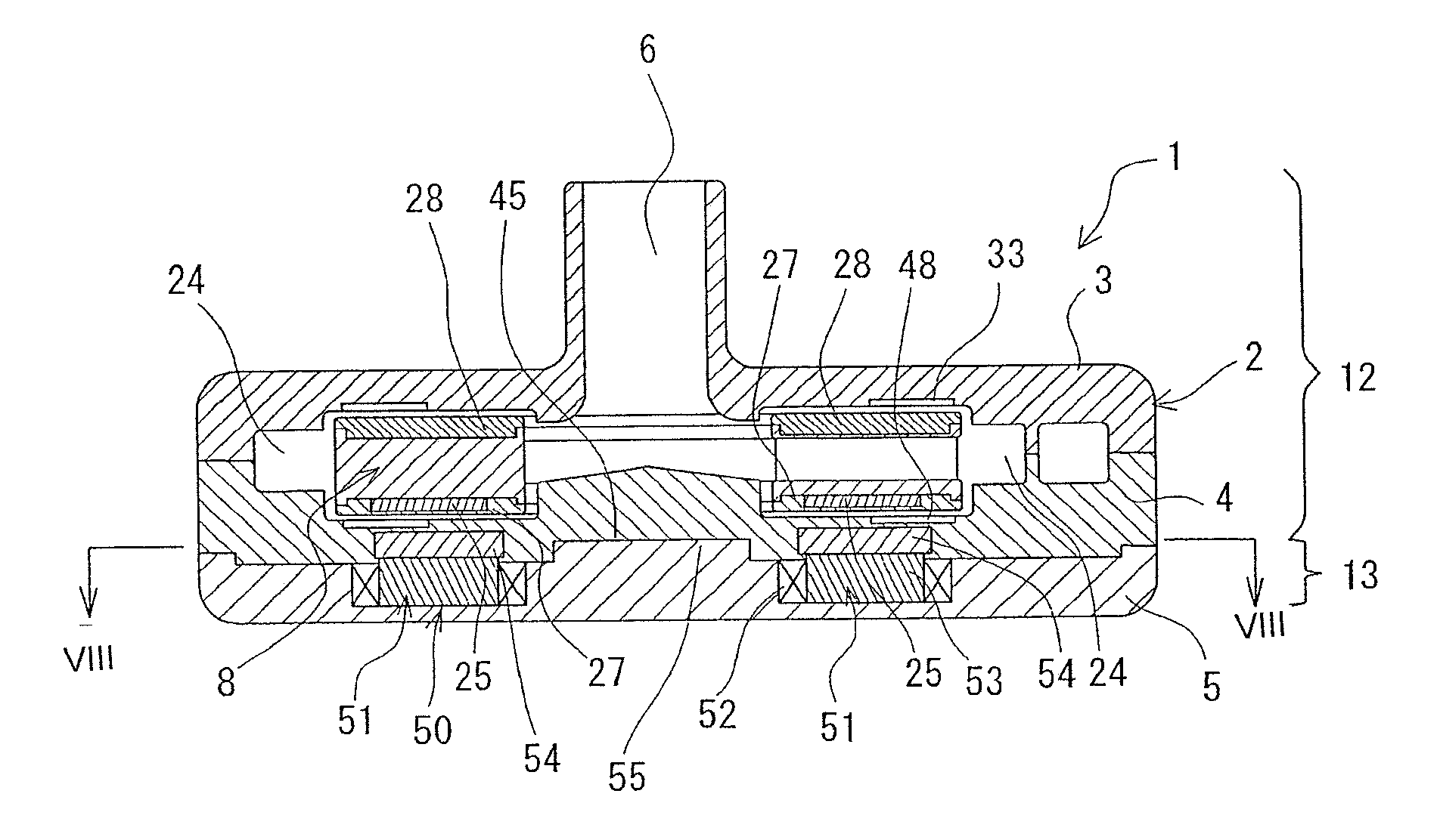
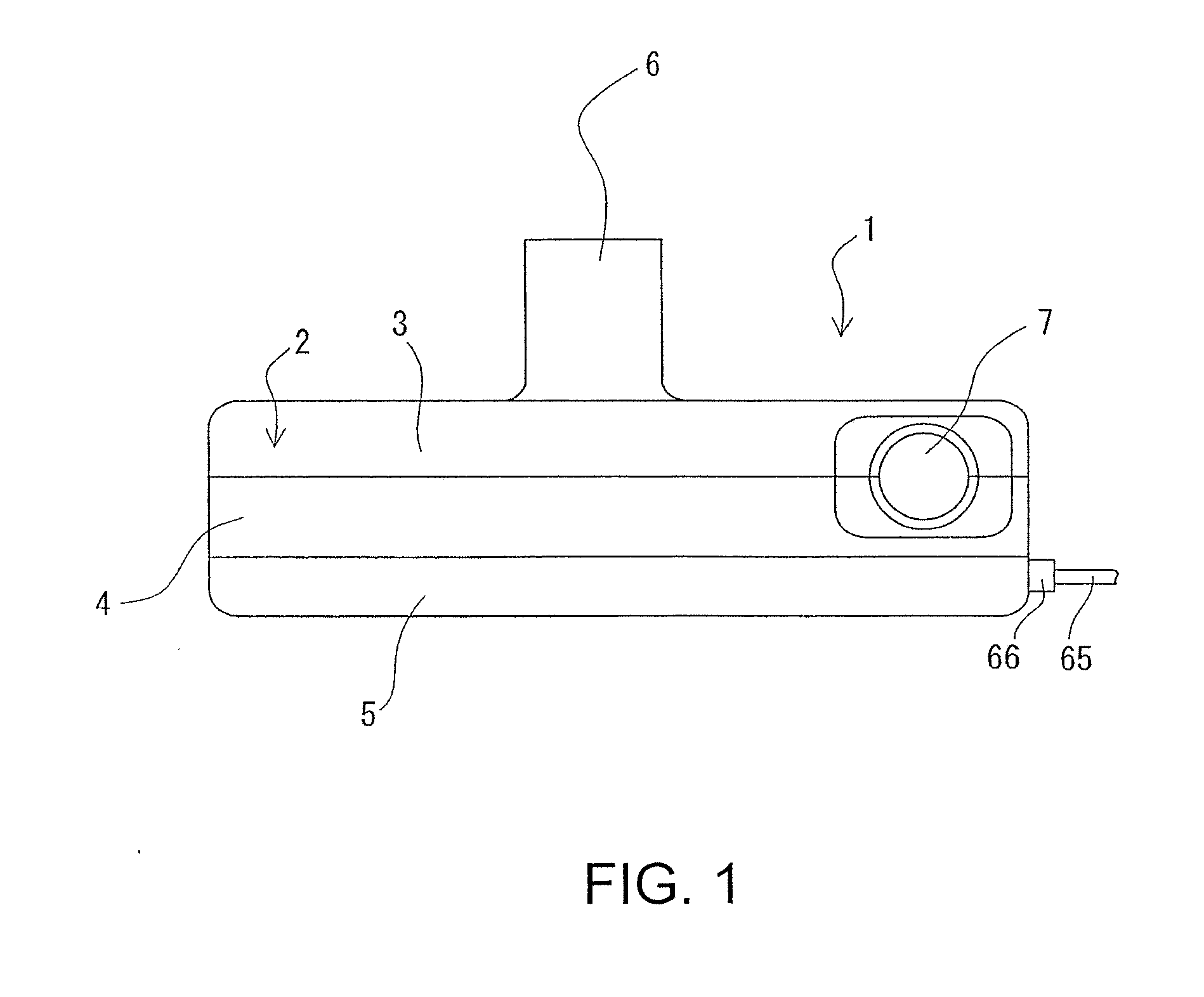
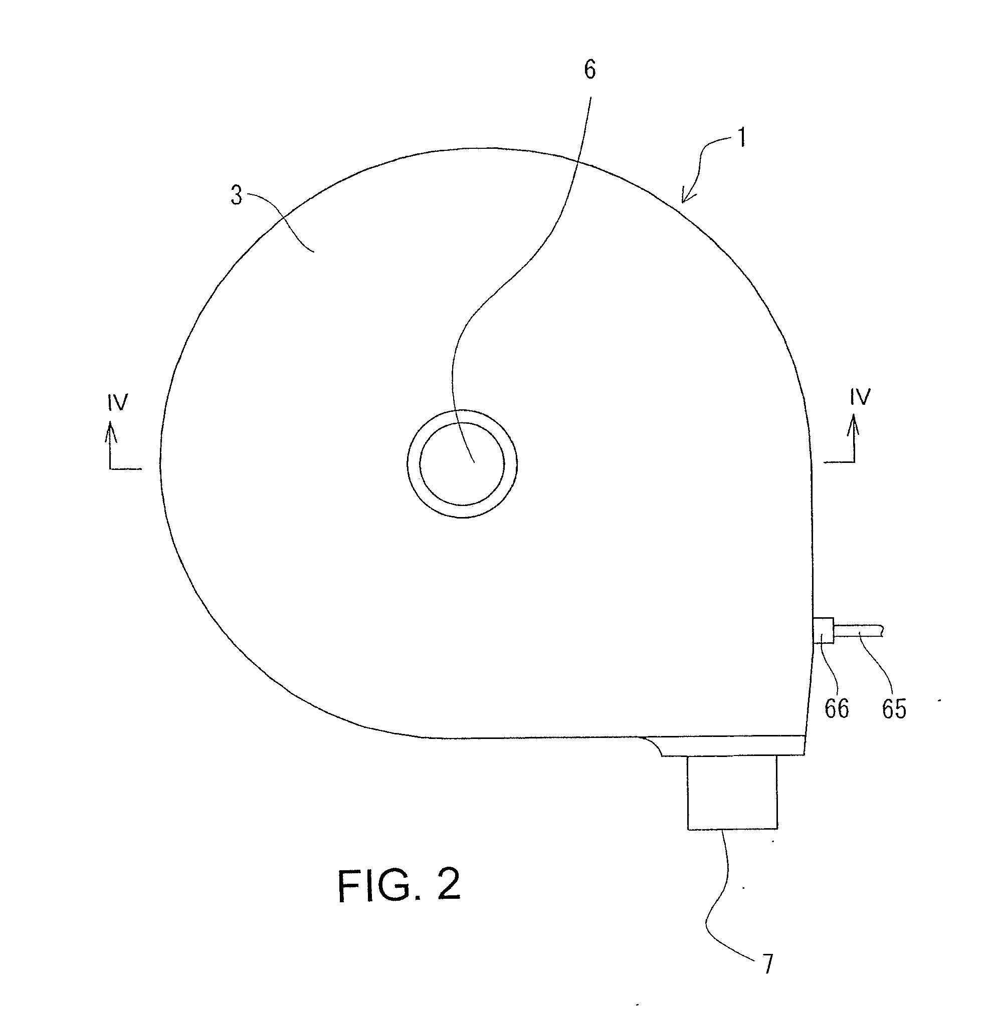
[0025]The embodiment of the blood pump apparatus 1 shown in FIGS. 1-8 includes: a housing 2 having a blood inlet port 6 and a blood outlet port7; a pump unit 12 specifically shown in FIG. 4 including an impeller 8 which has a plurality of magnetic materials (magnetic material bodies or pieces) 25 and which rotates within the housing to feed blood; and an impeller rotational torque generation section 13 for rotating the impeller. The housing 2 includes a plurality of magnetic members 54 embedded between the impeller 8 and the impeller rotational torque generation section 13 for transmitting a magnetically attractive force generated by the impeller rotational torque generation section 13 to the magnetic material bodies 25 of the impeller. The magnetic material bodies 54 are embedded in the housing 2 (second housing member 4) so that the magnetic material bodies 54 are positioned in respective recesses in the housing 2 (second housing member 4) and so that the magnetic material bodies ...


PUM


Abstract

A blood pump apparatus includes a housing having a blood inlet port and blood outlet port, a pump unit including an impeller that rotates within the housing, and an impeller rotational torque generation section. The housing includes a plurality of magnetic members embedded between the impeller and the impeller rotational torque generation section for transmitting a magnetically attractive force generated by the impeller rotational torque generation section to an impeller body. The pump device includes a non-contact bearing mechanism for rotating the impeller without contacting with the inner surface of the housing when the impeller is rotated by the impeller rotational torque generation section.

Description

CROSS-REFERENCES TO RELATED APPLICATIONS[0001]This application is a continuation of co-pending U.S. patent application Ser. No. 12 / 975,816, entitled “BLOOD PUMP APPARATUS,” filed on 22 Dec. 2010, which is a continuation of International Application No. PCT / JP2009 / 061318, filed on 22 Jun. 2009, which claims the benefit of Japanese Application No. 2008-163401, filed on 23 Jun. 2008, the complete disclosures of which are herein incorporated by reference for all intents and purposes.TECHNICAL FIELD[0002]The present invention generally pertains to blood pumps, more specifically a blood pump apparatus for feeding blood.BACKGROUND OF THE INVENTION[0003]Recently, there have been an increasing number of instances in which a centrifugal blood pump is used as a heart assisting pump for assisting a heart or for extracorporeal blood circulation in a pump-oxygenator. Proposals have been made of a centrifugal blood pump of the type embedded in a living body.[0004]One example of a centrifugal pump ...

Claims


Application Information

Patent Timeline
IPC IPC(8): F04D13/02A61M1/10
CPCA61M1/1036F04D13/026F04D13/0666F04D29/048F04D29/047A61M60/824A61M60/422A61M60/104A61M60/216A61M60/822A61M60/419
Inventor MORI, TAKEHISA
Owner TC1 LLC
Why Eureka
Try Eureka