Coil component

Pending Publication Date: 2022-10-27
MURATA MFG CO LTD
View PDF0 Cites 0 Cited by
  • Summary
  • Abstract
  • Description
  • Claims
  • Application Information

AI Technical Summary

Benefits of technology

[0013]According to the present disclosure, the filler contained in the cover member acts so as to provide the cover member with a predetermined thickness. As a result, a sufficient thicknesses of the portions of the cover member over the top surfaces of the first and second flanges can be provided.
[0014]Since the cover member having a sufficient thickness is formed over the top surfaces of the first and second flanges, the likelihood of crack generation can be reduced in the portion of the cover member that covers the wire wound around the winding core portion even if the cover member is subjected to a large compressive stress in the thermal shock testing. The reason behind this is probably that an increase in

Problems solved by technology

In other words, known coil components are not necessarily designed to be used in conditions requiring higher reliability, for example, for devices for vehicle.
In this case, cracks are sometimes generated in a portion of the cover member that covers the wire wound around t

Method used


Image

  • Coil component
  • Coil component
  • Coil component

Examples


first embodiment

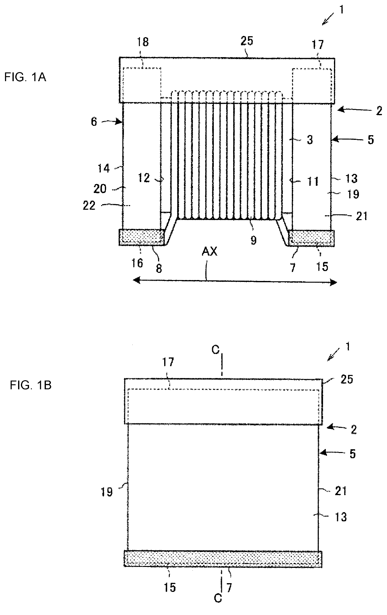
[0021]A coil component 1 according to the present disclosure will be described with reference to FIGS. 1A and 1B.

[0022]The coil component 1 includes a core 2. The core 2 has a winding core portion 3, a first flange 5, and a second flange 6. The winding core portion 3 extends in the axial direction AX. The first flange 5 and the second flange 6 are formed respectively at first and second ends of the winding core portion 3 that are positioned oppositely in the axial direction. The core 2 is shaped like a quadrangular prism as a whole. For example, a dimension of the core 2 in the axial direction AX is 0.5 to 2.6 mm, a height dimension thereof is 0.4 to 2.0 mm, and a width dimension is 0.3 to 2.3 mm. An example of the core 2 has a length of 1.6 mm in the axial direction AX, a height of 0.85 mm, and a width of 0.8 mm.

[0023]For example, the core 2 is made of a nonmagnetic material such as a ceramic insulator like alumina, a magnetic material like a nickel-zinc (Ni—Zn) based ferrite or a ...

second embodiment

[0059]FIG. 4 is a cross-sectional view illustrating a portion of a coil component 1a according to the present disclosure, in which the cover member 25 is formed so as to cover the top surface 17 of the flange 5. In FIG. 4, the elements corresponding to those illustrated in FIGS. 1A and 1B are denoted by the same reference signs, thereby omitting duplicated description.

[0060]The coil component 1a illustrated in FIG. 4 is characterized in that the inside surface 11 of the flange 5 of the core 2 inclines. The cover member 25 has a thick portion 37 over the inside surface 11 of the flange 5 located near the winding core portion 3. In the coil component 1a, stress is not concentrated easily in a portion of the cover member 25 at the border between the flange 5 and the winding core portion 3 compared with the coil component 1 of the first embodiment, which can reduce the likelihood of crack generation.

[0061]The present disclosure has been described in relation to embodiments illustrated i...


PUM


Abstract

A coil component includes a cover member containing an ultraviolet curable resin and a filler made of flat particles each having a major axis and a minor axis. The filler preferably contains talc particles. The particles of the filler contained in a portion of the cover member that covers a top surface of the flange are aligned to orient the major axes parallel or substantially parallel to the top surface. The filler contained in the portion of the cover member that covers the top surface has an area ratio of from 15.0% to 50.1% in a section of the cover member taken along a plane that passes through the central axis of a winding core portion and orthogonally intersects the top surface. The grain size of the particles of the filler in D50 is from 1 μm to 30 μm.

Description

CROSS-REFERENCE TO RELATED APPLICATION[0001]This application claims benefit of priority to Japanese Patent Application No. 2021-073700 filed Apr. 24, 2021, the entire content of which is incorporated herein by reference.BACKGROUNDTechnical Field[0002]The present disclosure relates to a coil component, and in particular, relates to a coil component that includes a core and a cover member, the core having a winding core portion around which a wire is wound and also having a first flange and a second flange formed at respective ends of the winding core portion, the cover member being formed so as to cover the core from a top surface of the first flange to a top surface of the second flange.Background Art[0003]For example, Japanese Unexamined Patent Application Publication No. 2008-10675 discloses a coil component that includes a core having a winding core portion around which a wire is wound and also having a first flange and a second flange formed respectively at a first end and a sec...

Claims


Application Information

Patent Timeline
IPC IPC(8): H01F27/02H01F27/30
CPCH01F27/02H01F27/306H01F17/04H01F2017/048H01F2017/0093H01F27/022H01F27/2823H01F27/292H01F17/045
Inventor SHIOKAWA, NOBORUHAYASHI, KEIICHIROU
Owner MURATA MFG CO LTD
Why Eureka
Try Eureka