Lighting device and illumination apparatus using same

a technology of lighting device and illumination apparatus, which is applied in the direction of lighting and heating apparatus, light source combination, instruments, etc., can solve the problems of excessive inrush current flow in the led group, and the switching element may be under stress, so as to avoid the greatest difference in voltage drop, reduce stress, and reduce the effect of voltage drop

Inactive Publication Date: 2015-05-28
PANASONIC INTELLECTUAL PROPERTY MANAGEMENT CO LTD
View PDF5 Cites 2 Cited by
  • Summary
  • Abstract
  • Description
  • Claims
  • Application Information

AI Technical Summary

Benefits of technology

[0010]In view of the above, the present disclosure provides an illumination apparatus and a lighting device for lighting a plurality of light sources to emit lights of different colors in a time-divisional manner so that stress to semiconductor light emitting elements and / or switching elements can be suppressed and an excessive current can be prevented from flowing the light sources.
[0046]Accordingly, stress exerted to a semiconductor light emitting element or a light source switch included in the series load circuit can be reduced.
[0047]Additionally, in accordance with the above aspects of the present invention, for example, among the at least three light sources, switching from the light source switch connected to the light source of the relatively great voltage drop to the light source switch connected to the light source of the relatively small voltage drop can be avoided. Further, the switching causing the greatest difference in voltage drops can be avoided. Accordingly, the greatest inrush current possibly occurring in series load circuits can be avoided and excessive inrush current can be suppressed. As a result, damage and stress to the light sources and the light source switches can be relieved, and the lifespan of the lighting device can be prolonged.
[0048]In the repeated predetermined order of switching the light source switches, among switching from the light source switch connected to the light source of the relatively great voltage drop to the light source switch connected to the light source of the relatively small voltage drop, the greatest inrush current are likely to occur at the time of switching when the difference in voltage drops becomes greatest. In accordance with the aspects of the present invention, since inrush current suppression control is conducted at the switching where the greatest inrush currents are likely to occur, damage and stress to the light sources and the light source switches can be relieved, and the lifespan of the lighting device can be prolonged.

Problems solved by technology

However, the above-mentioned time-divisional manner, in which the LEDs are lit time-divisionally while adjusting the duty ratio, has problems in that, when a LED group to which a power is supplied is changed sequentially, the switching element may be under stress or an excessive inrush current may flow in a LED group which is turned on by the changing.
Therefore, when the LED group to which the power is supplied is changed sequentially, the excessive inrush current may flow in the LED group turned on.

Method used


Image

  • Lighting device and illumination apparatus using same
  • Lighting device and illumination apparatus using same
  • Lighting device and illumination apparatus using same

Examples


first embodiment

Summary of First Embodiment

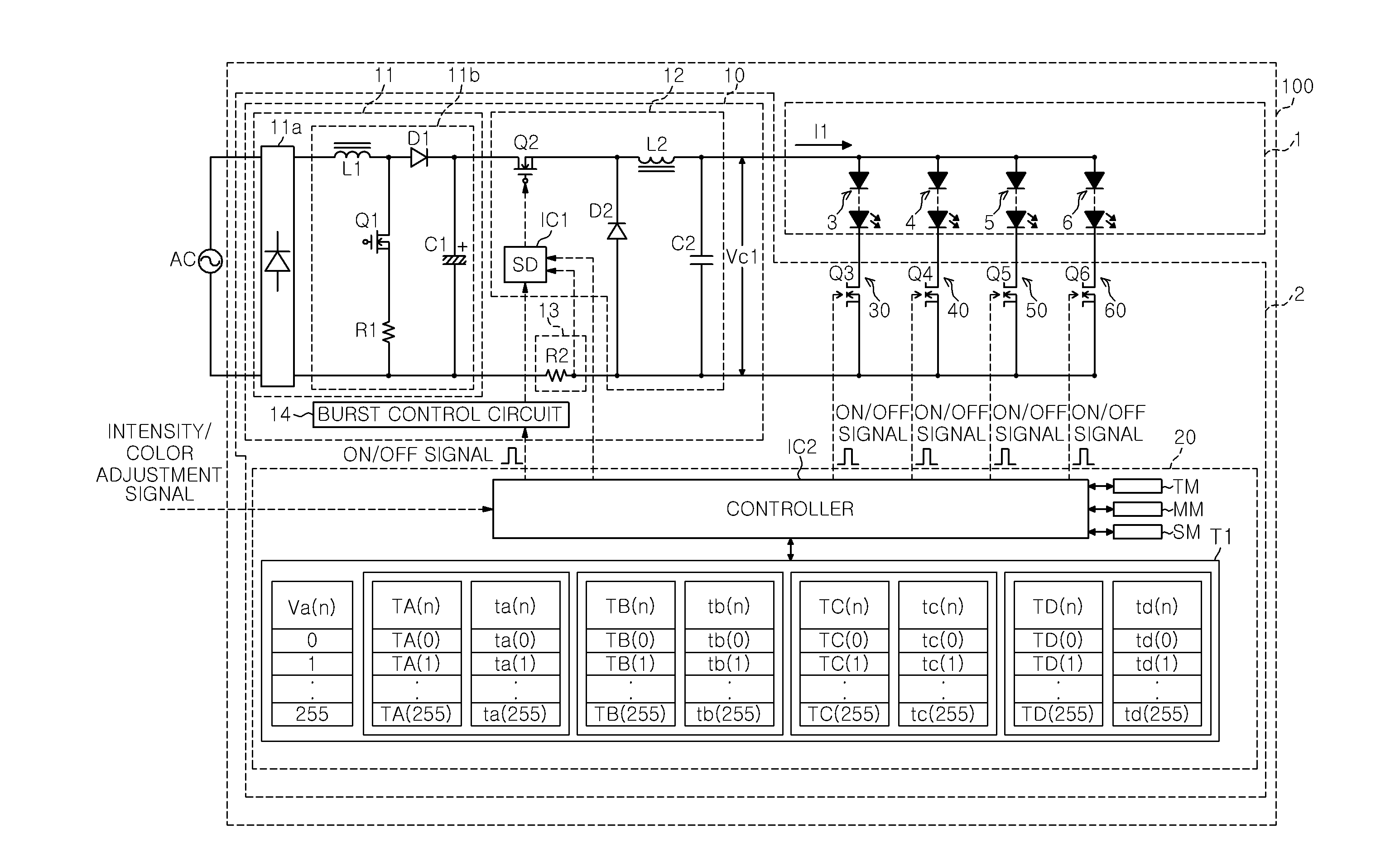
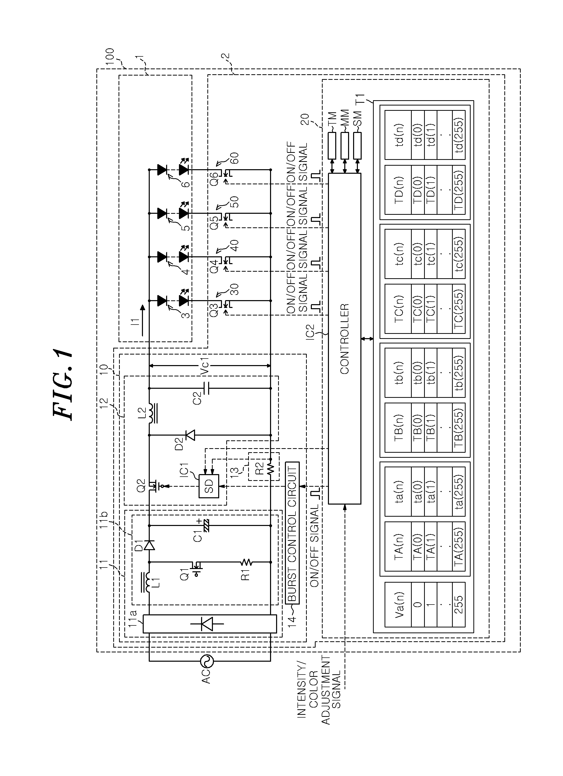
[0204]The illumination apparatus 100 includes: the DC power source circuit 11; the output control circuit 12 that adjusts an output current by performing a chopping operation to repeatedly turn on / off the switching element Q2 disposed on a power line connected between the DC power source circuit 11 and the light source unit 1; the light source unit 1 having LED groups 3 to 6 for emitting lights of different colors; and the control unit 20 that controls the current flowing in each of the LED groups 3 to 6. Further, the series load circuits 30, 40, 50 and 60 which include the LED groups 3 to 6 and the light source switches Q3 to Q6 respectively connected to the LED groups 3 to 6 in series are connected in parallel to the output terminals of the output control circuit 12.

[0205]In addition, in the lighting device 2 in accordance with the first embodiment, the control unit 20 adjusts the lengths of ON-periods of the light source switches Q3 to Q6. More specific...

second embodiment

[0328]FIG. 19 is a circuit block diagram of an illumination apparatus 300 in accordance with a second embodiment. In FIG. 19, the same elements as in the illumination apparatus 100 shown in FIG. 1 are denoted by the like numerals. The illumination apparatus 300 in accordance with the second embodiment has the same configuration as the illumination apparatus 100 in accordance with the first embodiment, except for that a discharge circuit 15 is connected between the output terminals of the output control unit 12 of the power unit 10 in a lighting device 302.

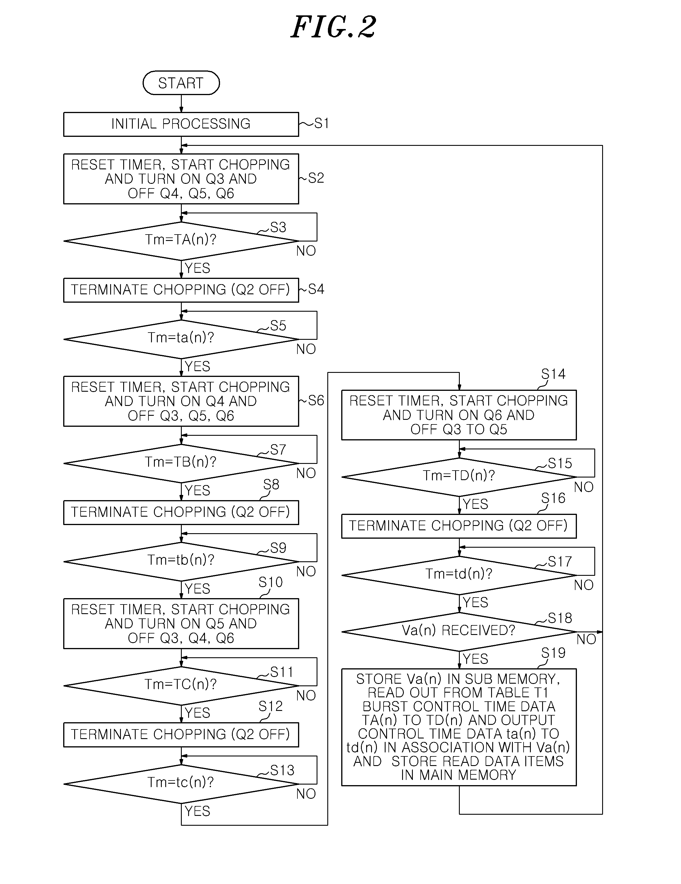
[0329]The operations of the illumination apparatus 300 are basically the same as those of the illumination apparatus 100 in accordance with the first embodiment. The control unit 20 performs control operations based on the flowchart in FIG. 2. The discharge circuit 15 provided in the power unit 10 is connected in parallel to four series load circuits 30, 40, 50 and 60. The discharge circuit 15 facilitates release of electric charge...

third embodiment

[0336]FIG. 20 is a circuit block diagram of an illumination apparatus 400 in accordance with the third embodiment. In FIG. 20, the same elements as in the illumination apparatus 100 shown in FIG. 1 are denoted by the like numerals.

[0337]The illumination apparatus 400 in accordance with the present embodiment has the same configurations as the illumination apparatus 100 in accordance with the first embodiment, except for that an inrush current suppression circuit 111 which is connected between output terminals of output control circuit 12 in parallel to the series load circuit 30, 40, 50 and 60. The inrush current suppression circuit 111 includes a resistor R4 as an impedance element and a switching element Q7 connected in series to the resistor R4.

[0338]The inrush current suppression circuit 111 is connected between the output terminals of the output control circuit 12 in parallel to the series load circuits 30, 40, 50 and 60. When the switching element Q7 is turned on, electric cha...


PUM


Abstract

A lighting device includes: a DC power source circuit; an output control circuit including a chopping switch to adjust an output current by chopping of the chopping switch; light source switches respectively connected to the light sources; and a control unit for controlling a time period for which a current flows in the light sources. The control unit controls the output control circuit such that an operation period for which the chopping is conducted and a stop period for which the chopping is stopped are repeated alternately and performs switchover of the light source switches to be sequentially and selectively turned on, and the switchover is conducted during the stop period with a time interval from a beginning of the stop period.

Description

CROSS-REFERENCE TO RELATED APPLICATION[0001]This application claims priority to Japanese Patent Application Nos. 2013-246032, 2013-246033 and 2013-246034 filed on Nov. 28, 2013, the entire contents of which are incorporated herein by reference.TECHNICAL FIELD[0002]The present disclosure relates to a lighting device for lighting light sources of different colors to emit a light and to an illumination apparatus using the lighting device.BACKGROUND ART[0003]Recently, an illumination apparatus is used that includes a lighting device for lighting a light source unit having groups of semiconductor light emitting elements such as LEDs (Light Emitting Diodes) for emitting lights of different colors including green, blue, red or the like.[0004]In such an illumination apparatus, the chromaticity or intensity of a combined light emitted therefrom can be adjusted by adjusting the intensity of light emitted from each LED group.[0005]There is known a lighting device used in the illumination appar...

Claims


Application Information

Patent Timeline
Patent Type & Authority Applications(United States)
IPC IPC(8): H05B33/08F21V23/00F21V23/02F21K99/00F21V23/04H05B44/00
CPCH05B33/08F21K9/00F21V23/04F21Y2105/00F21V23/004F21Y2101/02F21V23/02F21S8/026F21S8/038F21Y2115/10F21Y2113/13H05B45/46H05B45/38H05B47/165H05B45/375H05B45/24H05B47/25Y02B20/30
Inventor HASEGAWA, JUNICHIHIRAMATU, AKINORIIDO, SHIGERU
Owner PANASONIC INTELLECTUAL PROPERTY MANAGEMENT CO LTD
Why Eureka
Try Eureka