Light source control device and light source control method

a technology of light source control and control device, which is applied in the direction of lighting apparatus, light sources, electroluminescent light sources, etc., can solve the problems of not being able to detect faults and affecting the operation of leds in all directions

Active Publication Date: 2017-08-22
MITSUBISHI ELECTRIC CORP
View PDF24 Cites 0 Cited by
  • Summary
  • Abstract
  • Description
  • Claims
  • Application Information

AI Technical Summary

Benefits of technology

[0007]It is an object of the present invention to provide a light source control device capable of detecting a fault in light sources due to an open fault and preventing an excessive current from flowing through the other normal light sources in which no fault occurs and to provide a light source control method.
[0010]The light source control device includes the current supply unit that collectively supplies a current to the plurality of light sources, the current detector that divides the plurality of light sources into groups and detects a current amount of a current supplied to each of the groups, the fault detector that detects an open fault in the light sources on the basis of a ratio of the current amount in each of the groups, and the controller that controls a current supplied from the current supply unit to be reduced in a case where the fault detector detects an open fault in the light sources. Therefore, the fault in the light sources due to the open fault can be detected, and the excessive current can be prevented from flowing through the other normal light sources in which no fault occurs.

Problems solved by technology

However, a fault cannot be detected because when the light goes out due to an open fault, the other normal LEDs in which no fault occurs continue to light up.
This may cause a further fault, and faults may occur in all of the LEDs.

Method used


Image

  • Light source control device and light source control method
  • Light source control device and light source control method
  • Light source control device and light source control method

Examples


embodiment

Preferred Embodiment

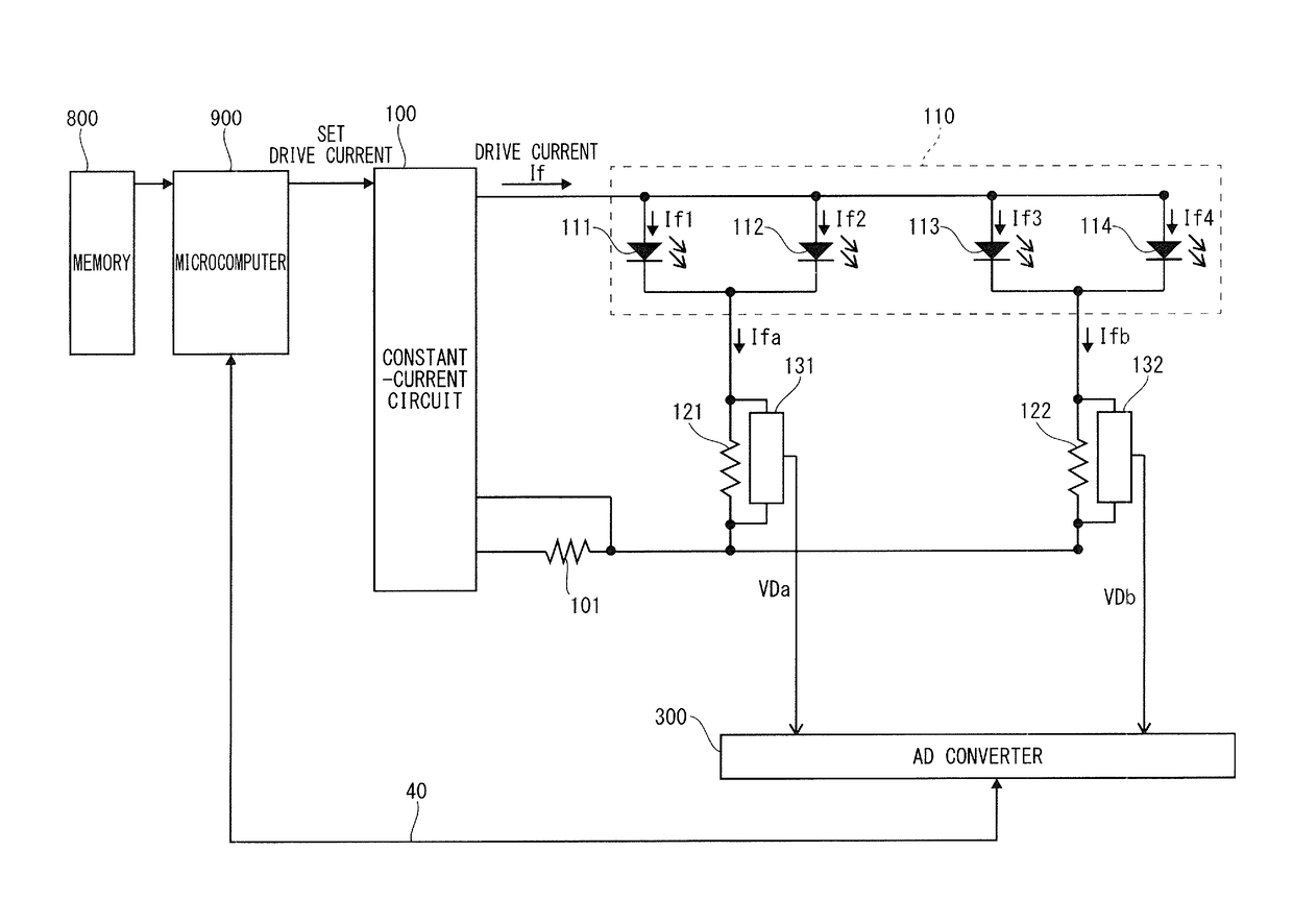
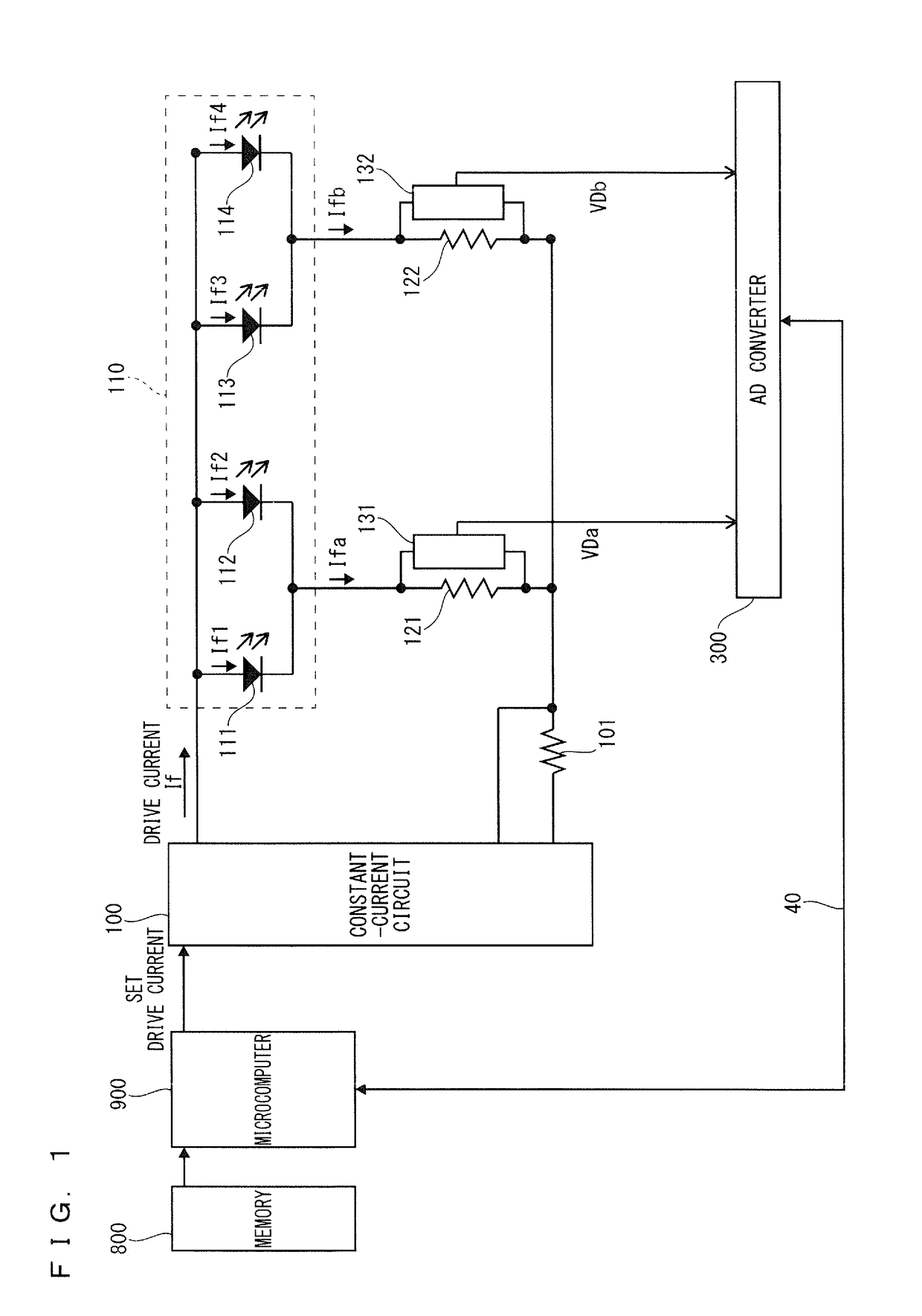
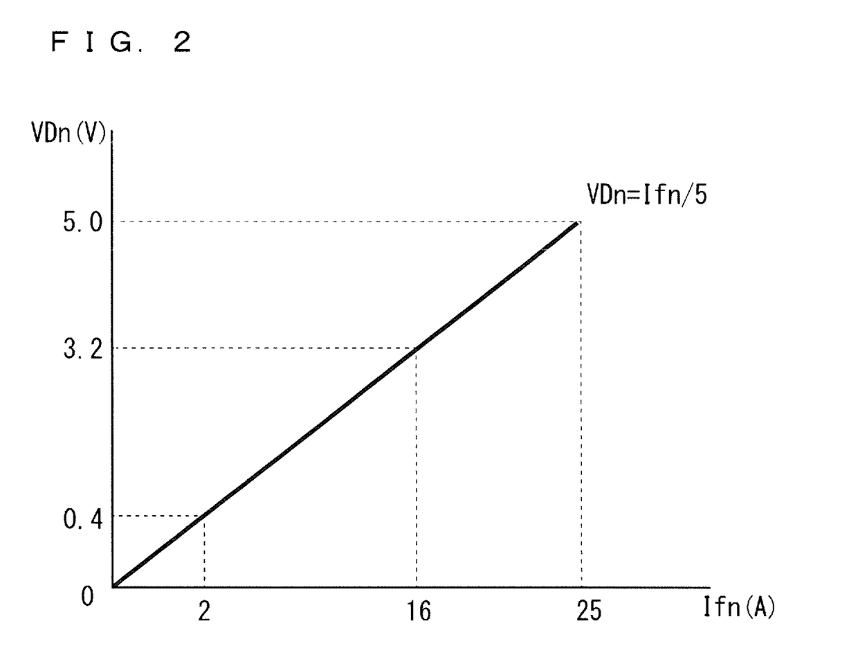
[0023]A preferred embodiment of the present invention is described below with reference to diagrams. FIG. 1 is a block diagram showing a configuration of a light source control device according to the preferred embodiment, FIG. 2 is a graph showing characteristics of current detection circuits 131, 132, and FIG. 3 is a chart (conversion table) showing the characteristics of the current detection circuits 131, 132.

[0024]As shown in FIG. 1, the light source control device controls LEDs 111, 112, 113, 114 being a plurality of light sources connected in parallel. The light source control device includes a microcomputer 900, a memory 800, a constant-current circuit 100, a detection resistor 101, the LEDs 111, 112, 113, 114, detection resistors 121, 122, the current detection circuits 131, 132, and an AD converter 300.

[0025]The microcomputer 900 is, for example, a microcomputer such as the MPU. The microcomputer 900 controls the constant-current circuit 100, includes a...


PUM


Abstract

A light source control device includes a constant-current circuit that collectively supplies a current to a plurality of LEDs, a current detection circuit that divides the plurality of LEDs into groups and detects a current amount of a current supplied to each of the groups, and a microcomputer that detects an open fault in the LEDs on the basis of a ratio of the current amount in each of the groups and controls a current supplied from the constant-current circuit to be reduced in a case where an open fault is detected in the LEDs.

Description

BACKGROUND OF THE INVENTION[0001]Field of the Invention[0002]The present invention relates to a light source control device and a light source control method in a case where a plurality of light sources, such as light emitting diodes (hereinafter referred to as “LEDs”) or lasers, are used.[0003]Description of the Background Art[0004]In recent times, as light sources of projection video display devices, an aggregation of a plurality of LEDs connected in parallel have been developed to be used. The advantage of the parallel-connected LEDs is that the large number of LEDs can be driven at low voltage and that light sources in high luminance can be obtained by lighting the plurality of LEDs. Thus, in comparison to devices including conventional lamp light sources, the devices including the light sources formed of the plurality of LEDs connected in parallel can suppress power consumption of the whole devices.[0005]The LEDs have been known that vary in luminance according to a drive curre...

Claims


Application Information

Patent Timeline
Patent Type & Authority Patents(United States)
IPC IPC(8): H05B37/02H05B33/08H05B44/00
CPCH05B33/0848H05B33/0827H05B45/14H05B45/46H05B47/00
Inventor YONEOKA, ISAOASAMURA, YOSHINORIYAMAMOTO, ZENKOUINOUE, HARUHISA
Owner MITSUBISHI ELECTRIC CORP
Why Eureka
Try Eureka