Eureka AIR delivers breakthrough ideas for toughest innovation challenges, trusted by R&D personnel around the world.

Material conveying device capable of avoiding output pressure change and automatically adjusting pressure

A technology of automatic pressure regulation and output pressure, which is applied in the field of material conveying devices, can solve the problems of uneven plastic solution delivery, uneven thickness of plastic products, and affecting product quality, and achieve the effects of stable pressure, material saving, and uniform discharge

Inactive Publication Date: 2021-12-24
何付平
View PDF0 Cites 0 Cited by
  • Summary
  • Abstract
  • Description
  • Claims
  • Application Information

AI Technical Summary

Problems solved by technology

[0005] Aiming at the deficiencies of the prior art, the present invention provides a feeding device that avoids output pressure changes and automatically adjusts the pressure, which can automatically reduce the pressure of the discharge bin when the internal solution increases, prevent the solution from flowing too fast, and save material, and can stabilize the internal pressure by increasing the air pressure when the inflow rate of the solution inside the discharge bin decreases, making the discharge more uniform and realizing the advantages of automatic pressure regulation, which solves the problem that the delivery of the plastic solution is not uniform enough, and It is impossible to increase the pressure inside the injection nozzle, resulting in different thicknesses of the molded plastic products, affecting the quality of the product, and causing a large waste of materials

Method used


Image

  • Material conveying device capable of avoiding output pressure change and automatically adjusting pressure
  • Material conveying device capable of avoiding output pressure change and automatically adjusting pressure
  • Material conveying device capable of avoiding output pressure change and automatically adjusting pressure

Examples


Embodiment Construction

[0024] The following will clearly and completely describe the technical solutions in the embodiments of the present invention with reference to the accompanying drawings in the embodiments of the present invention. Obviously, the described embodiments are only some, not all, embodiments of the present invention. Based on the embodiments of the present invention, all other embodiments obtained by persons of ordinary skill in the art without making creative efforts belong to the protection scope of the present invention.

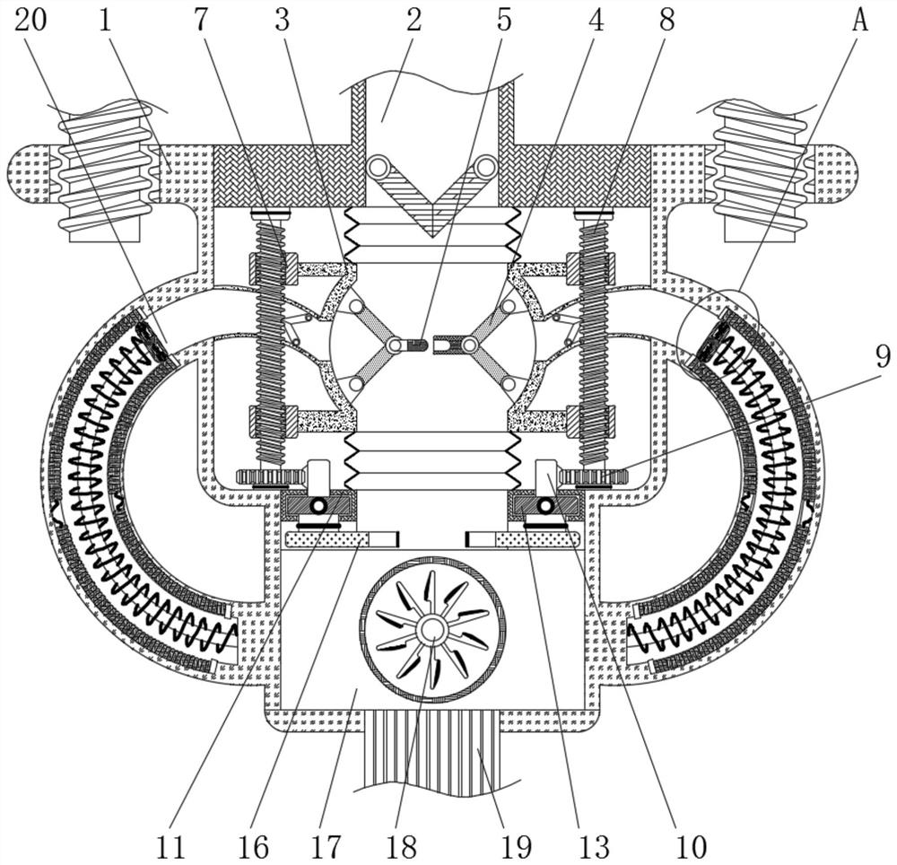
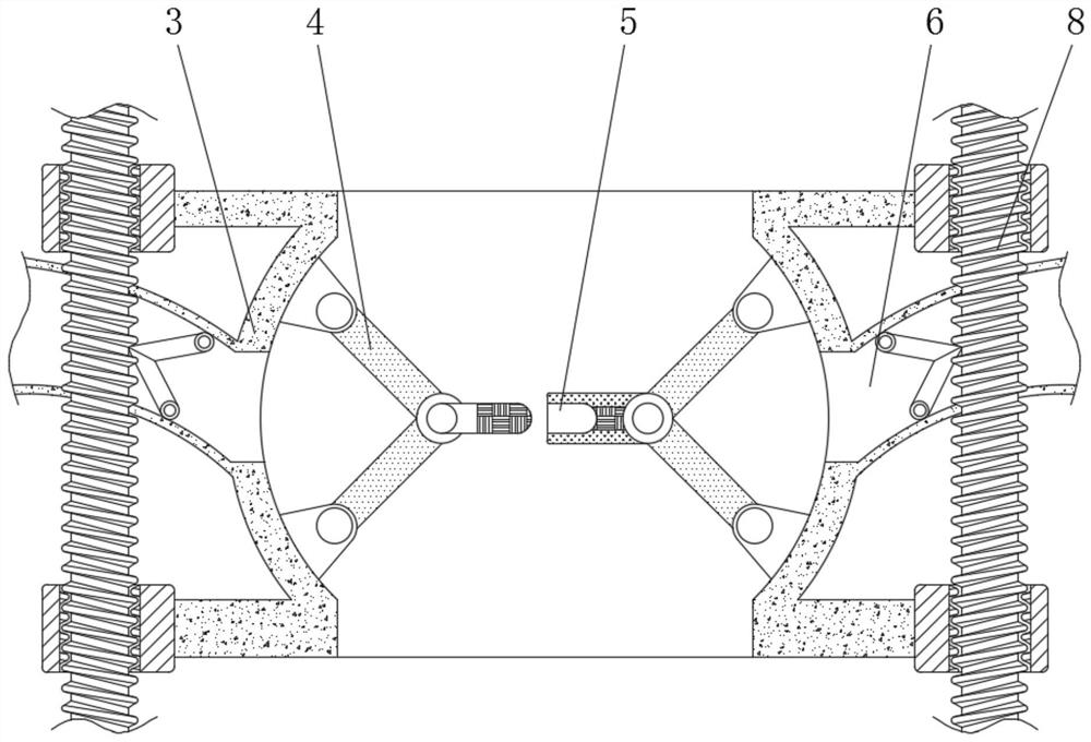
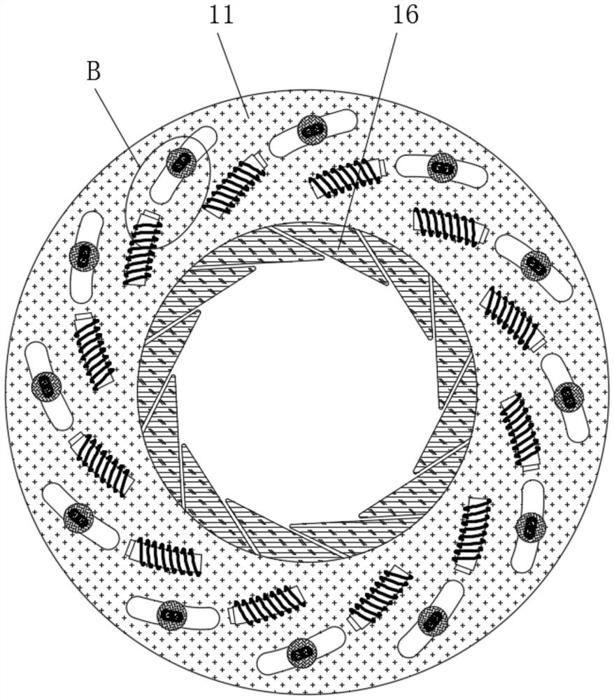
[0025] see Figure 1-5 , a feeding device that avoids output pressure changes and automatically adjusts pressure, including a frame 1, bolts are threaded on both sides of the upper end of the frame 1, and a one-way liquid valve is connected to the inside of the feed port 2 so that the external solution It can flow into the inside of the frame 1 in one direction to prevent the backflow of the solution. The upper end of the frame 1 is provided with a feed port 2...


PUM


Abstract

The invention relates to the technical field of toy accessories, and discloses a material conveying device capable of avoiding output pressure change and automatically adjusting pressure. The material conveying device comprises a rack, a feeding port is formed in the upper end of the rack, an elastic cavity is fixedly connected to the interior of the rack, a movable connecting rod is rotatably connected to the interior of the elastic cavity, a metal feeler lever is fixedly connected to the end part of the movable connecting rod, a hose is fixedly connected to the outer side wall of the elastic cavity, an inner threaded sleeve is fixedly connected to the outer side of the elastic cavity, a threaded rod is in threaded connection with the interior of the inner threaded sleeve, and a transmission gear is fixedly connected to the bottom end of the threaded rod. The resistance inside an electromagnetic rod is reduced, the electromagnetic rod and a magnetic block repel each other, a sliding block is pushed to slide, a baffle is driven to move, the area of a through hole input into the discharging bin is reduced, and the feeding amount is reduced, so that the effects that when the internal solution is increased, the pressure intensity of the discharging bin is automatically reduced, over-speed flowing of the solution is prevented, and materials are saved are achieved.

Description

technical field [0001] The invention relates to the technical field of toy accessories, in particular to a feeding device that avoids changes in output pressure and automatically regulates pressure. Background technique [0002] Toy manufacturing generally uses injection molding to manufacture plastic products of various shapes. During the injection molding process, due to the uneven delivery of the plastic solution and the inability to increase the pressure inside the injection nozzle, the formed plastic products are thick and thin. Inconsistency affects the quality of the product and causes a lot of waste of materials. [0003] In order to solve the above problems, the inventor provides a feeding device that avoids output pressure changes and automatically adjusts the pressure. The slide plate is pressed by the internal solution, so that the movable block slides to the inside of the resistance bar, and the resistance inside the electromagnetic rod is connected. The electr...

Claims


Application Information

Patent Timeline
Patent Type & Authority Applications(China)
IPC IPC(8): B29C45/58B29C45/20
CPCB29C45/581B29C45/20
Inventor 何付平
Owner 何付平
Why Eureka
Eureka Blog
Learn More