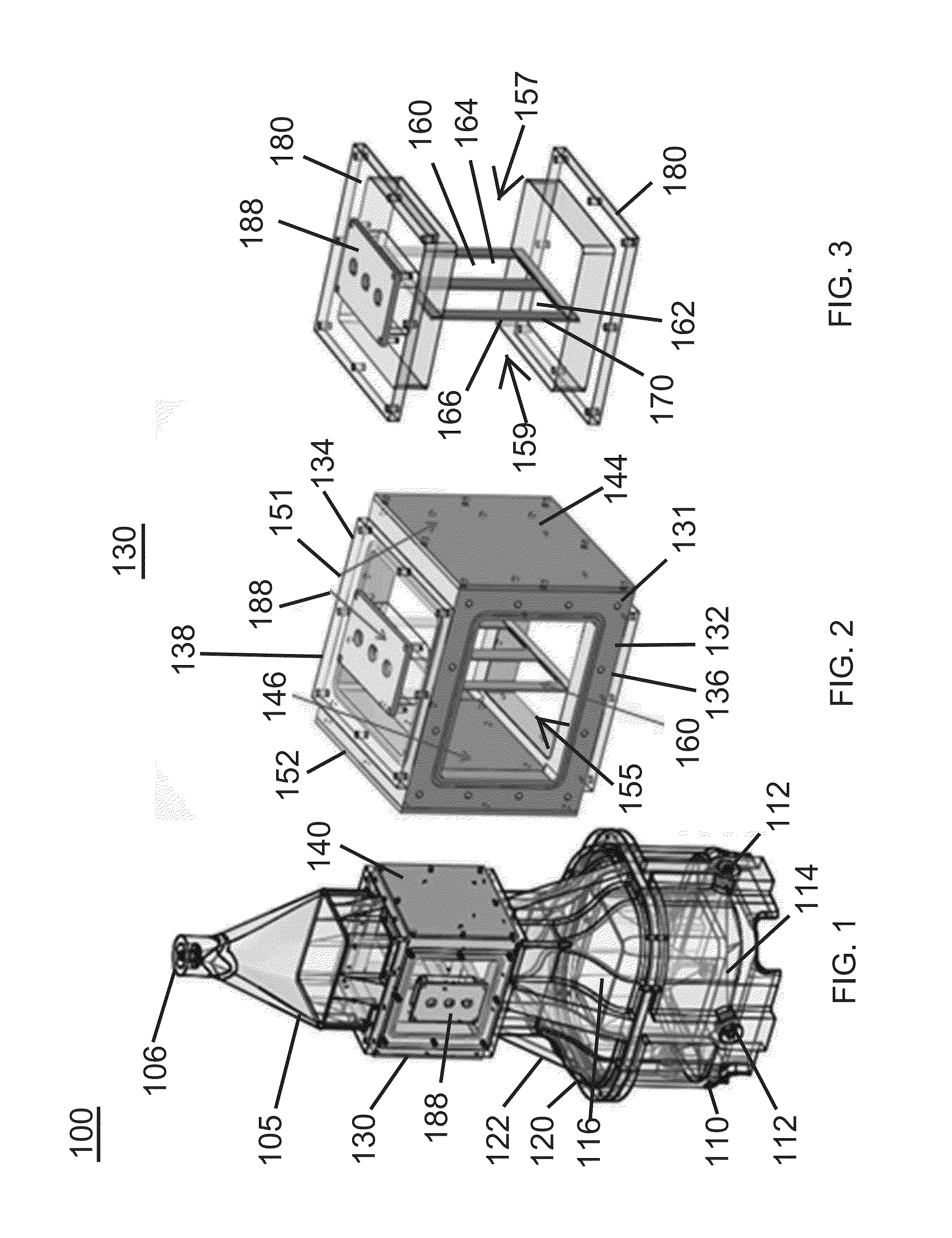
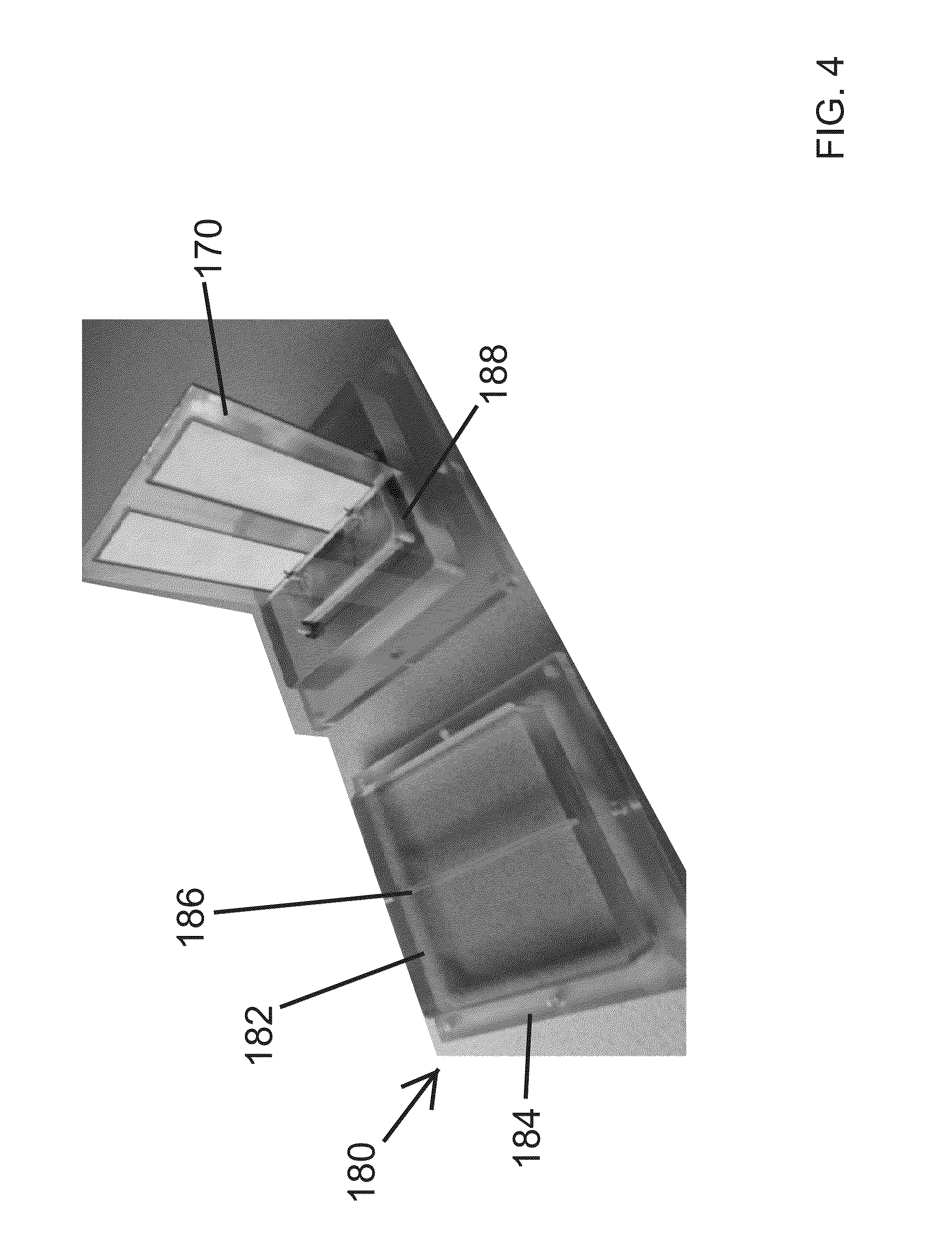
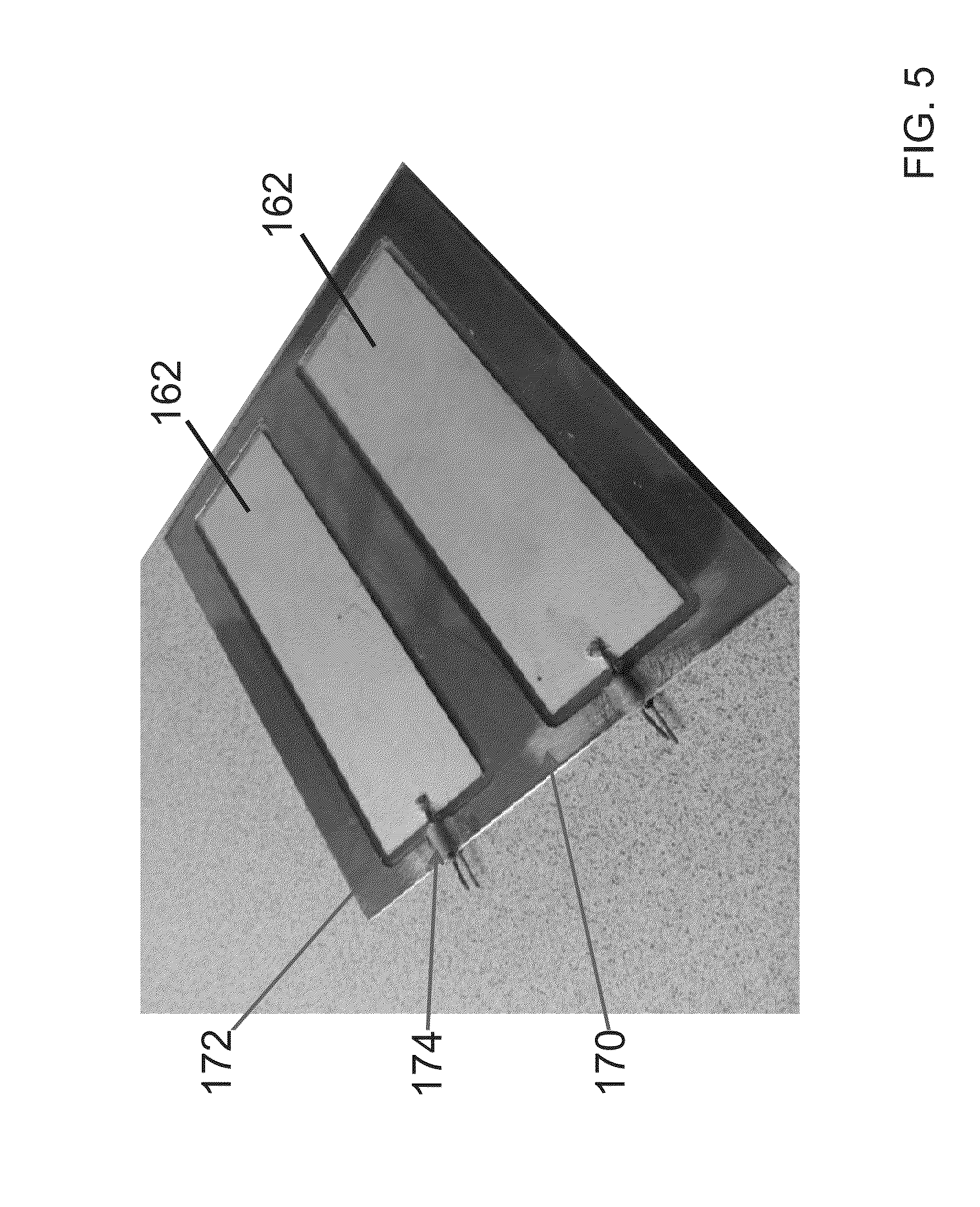
Acoustophoresis device with dual acoustophoretic chamber
a technology of acoustophoretic chamber and acoustophoretic chamber, which is applied in the field of acoustophoretic device with dual acoustophoretic chamber, can solve the problems of heat generation being deleterious to materials in the fluid stream, and the efficacy of conventional acoustophoretic devices is limited, so as to eliminate acoustic streaming
- Summary
- Abstract
- Description
- Claims
- Application Information
AI Technical Summary
Benefits of technology
Problems solved by technology
Method used
Image

Examples
examples
[0089]A conventional acoustophoresis device was used as a Comparative Example. This device used an acoustic chamber in which the ultrasonic transducer was located on one wall of the chamber, and a reflector was located on the opposite wall. The transducer had one piezoelectric crystal of dimensions 1 inch×3 inches.
[0090]An acoustophoresis device of the present disclosure is labeled as Example. This device used an acoustic chamber in which the piezoelectric crystal was mounted in the middle of the acoustic chamber. Two reflectors were located on opposite walls, parallel to the face of the one piezoelectric crystal. This piezoelectric crystal also had dimensions 1 inch×3 inches.
[0091]The two devices were then operated with a yeast slurry as the feed input. The slurry contained 0.5% solids. The devices were operated over 40 minutes of operation. FIG. 11 is a picture illustrating operation of the dual acoustophoresis chamber. The trapping lines generated by the piezoelectric element loc...
PUM
| Property | Measurement | Unit |
|---|---|---|
| frequency | aaaaa | aaaaa |
| Reynolds number | aaaaa | aaaaa |
| resonance frequency | aaaaa | aaaaa |
Abstract
Description
Claims
Application Information
 - R&D Engineer
- R&D Manager
- IP Professional
- Industry Leading Data Capabilities
- Powerful AI technology
- Patent DNA Extraction
Browse by: Latest US Patents, China's latest patents, Technical Efficacy Thesaurus, Application Domain, Technology Topic.
© 2024 PatSnap. All rights reserved.Legal|Privacy policy|Modern Slavery Act Transparency Statement|Sitemap