Multiple Air Chamber Foam Pump

Active Publication Date: 2015-07-30
OP HYGIENE IP GMBH
View PDF4 Cites 19 Cited by
  • Summary
  • Abstract
  • Description
  • Claims
  • Application Information

AI Technical Summary

Benefits of technology

[0039]in a cycle of operation in the withdrawal stroke, an axial distance between the first outer air sealing annular flange and the first outer air sealing disc increases thereby increasing a volume of the first outer air compartment and drawing air into the first outer air compartment and, in the retra

Problems solved by technology

The inventor of the present application has appreciated that previously known foam piston pumps suffer the disadvantage that the pumps typically cannot be inserted through a relatively small opening into a reservoir and have a reasonable stroke length while allowing an adequate volume of air to be displaced as to allow the product

Method used


Image

  • Multiple Air Chamber Foam Pump
  • Multiple Air Chamber Foam Pump
  • Multiple Air Chamber Foam Pump

Examples


Example

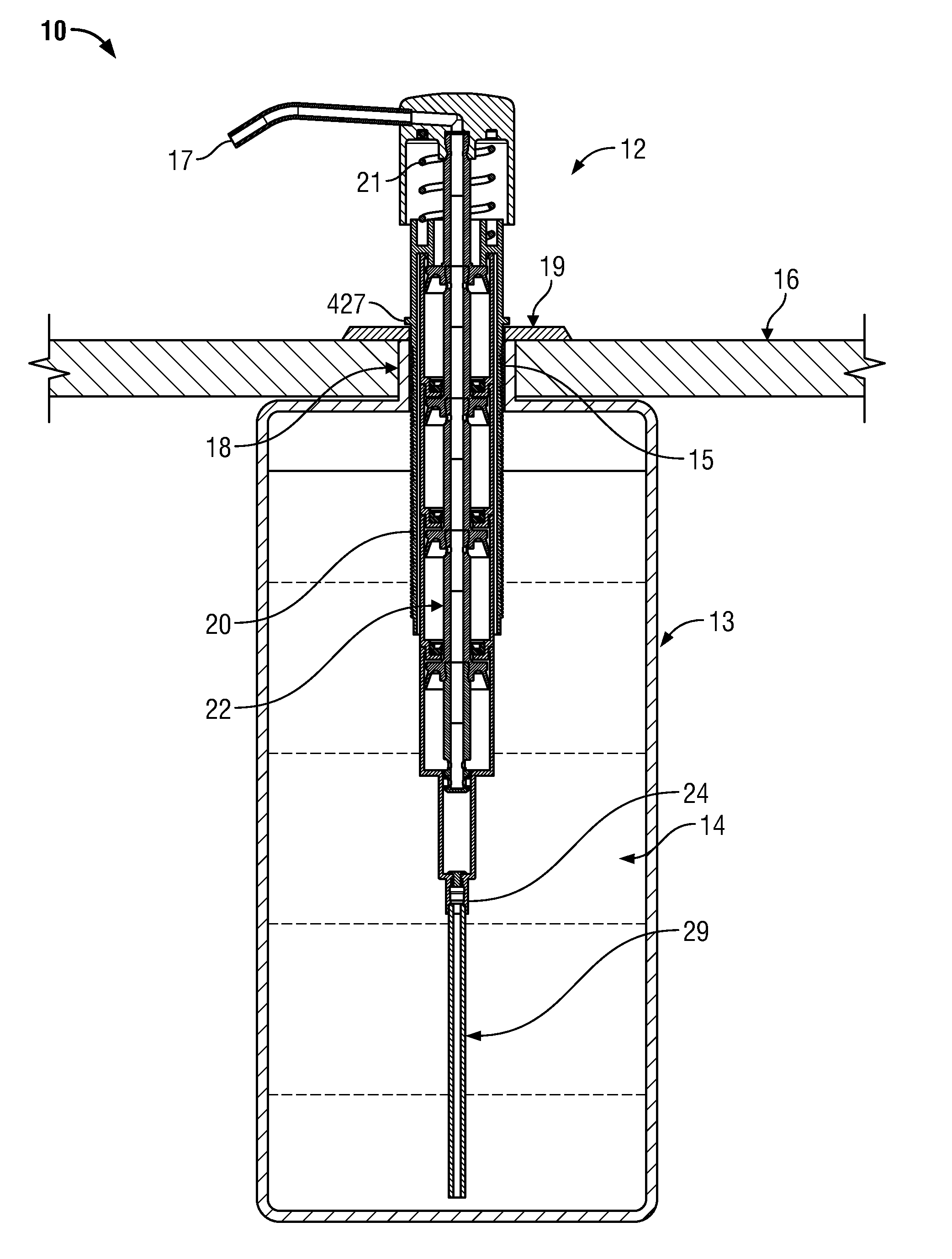
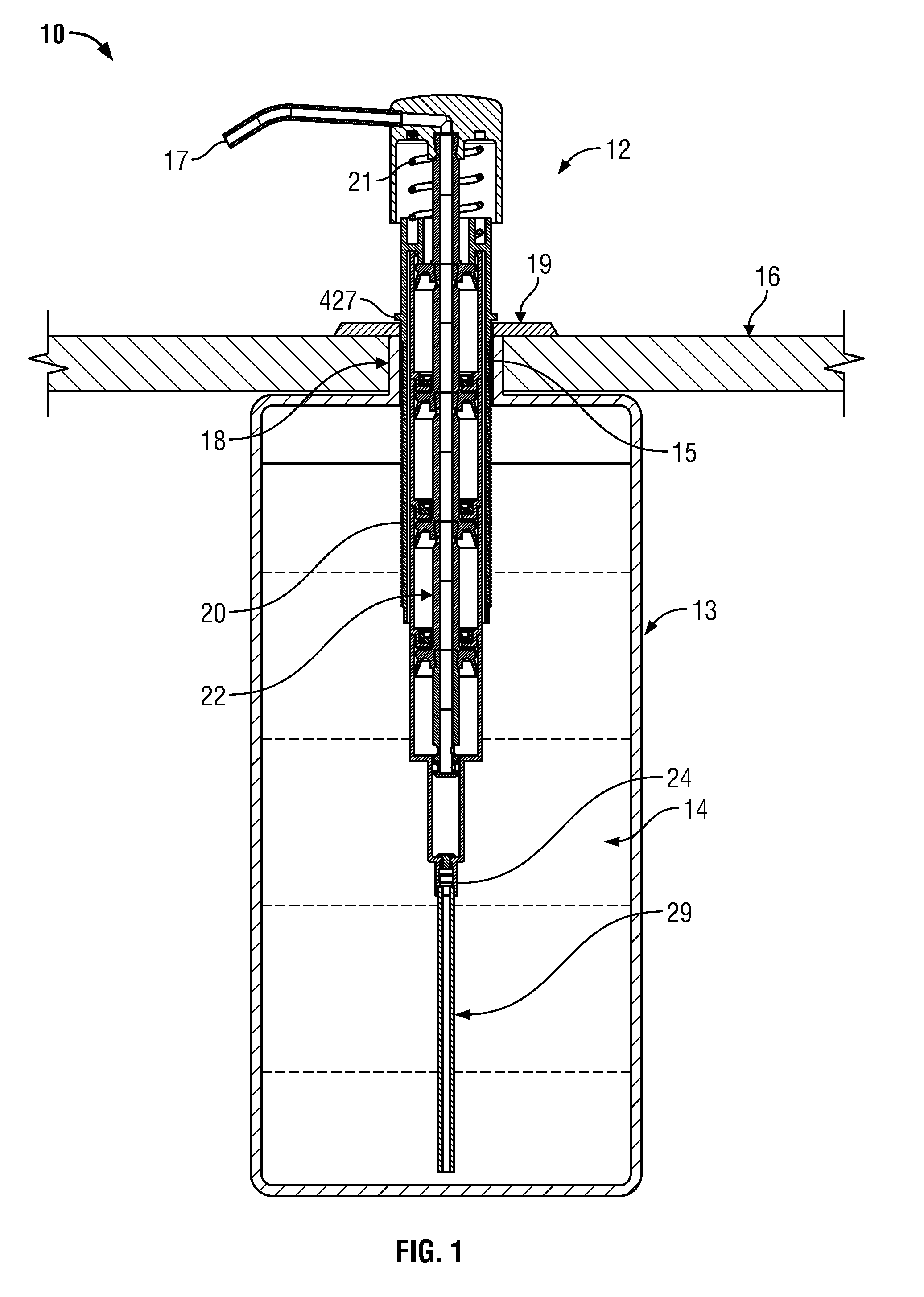
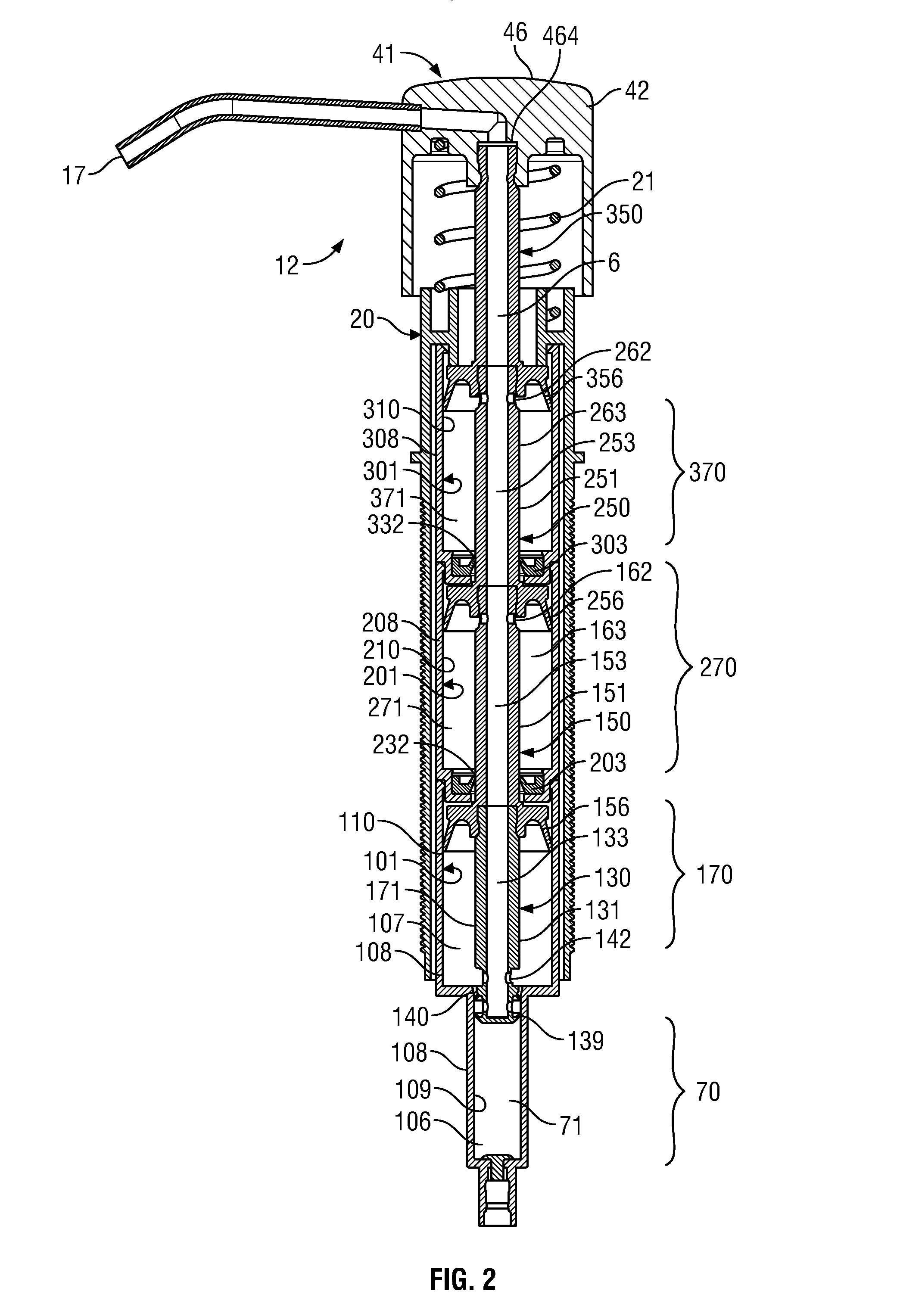
[0101]In the first embodiment illustrated in FIGS. 1 to 11, each of the liquid pump 70, the lower air pump 170, the first upper air pump 270 and the second upper air pump 370 are all in phase such that they, in a retraction stroke, simultaneously discharge fluid from their respective compartments and, in a retraction stroke, simultaneously draw fluid into their respective compartments. Thus, for example, advantageously in a retraction stroke, a unit dosage of liquid is discharged into the passageway 63 by the liquid pump 70 and, simultaneously, a volume of air is discharged from each of the air pumps 170, 270 and 370 so as to provide for the discharge of liquid and air simultaneously through the air forming member 464 forming foam which is discharged out the discharge outlet 17.

[0102]In a withdrawal stroke, fluid, notably air, is withdrawn from the discharge outlet 17 through the passageway 63 and into each of the second upper air compartment 371, the first upper air compartment 271...

Example

[0103]Reference is made to FIG. 12 which illustrates a second embodiment of a pump 10 in accordance with the present invention which is identical to the pump of the first embodiment, however, with the exception that the second upper air pump 370 has been eliminated by elimination from the pump 10 of the first embodiment as seen in FIG. 2 of the second upper casing assembly 300 and the first upper air piston 250.

Example

[0104]Reference is made to FIG. 13 which illustrates a third embodiment of a pump 10 in accordance with the present invention which is identical to the pump illustrated in FIG. 2, however, in which a third upper air pump 570 is provided by providing a third upper casing assembly 500 with a third upper casing 501 and a third upper air piston 550 which are modular and substantially the same as, respectively, the second upper casing assembly 300 and the first upper air piston 250.

[0105]A feature of the invention is that the pumps are configured to be made from modular components. The first upper casing assembly 200 and the second upper casing assembly 300 are identical in their casings 201 and 301 and in their first and second upper annular seal disc 203 and 303. The lower air piston 150 and the first upper air piston 250 are identical. The second upper air piston 350 is identical to the lower air piston 150 with the exception that there is no equivalent on the second upper air piston ...


PUM


Abstract

An improved foam piston pump in which a multiple of air pumps are disposed coaxially about a piston member and spaced axially along the piston member, preferably coaxially with a liquid pump for discharging air and liquid as foam. Each air pump is preferably provided by a modular piston within a modular casing assembly such that arrangements with one, two or more identical air pumps can be assembled from a plurality of the same modular components.

Description

SCOPE OF THE INVENTION[0001]This invention relates to foam pumps for dispensing liquid mixed with air as a foam and, more particularly, to a piston pump with multiple axially spaced air pumps.BACKGROUND OF THE INVENTION[0002]Liquid piston pumps for dispensing liquid through a countertop from a reservoir disposed below the countertop are known in which the body of the pump is inserted through an opening in the countertop into a reservoir, with merely an actuator and discharge outlet above the countertop. These liquid pumps are operative in a single stroke as to allow the production of a desired unit dosage volume of liquid. The opening through the countertop is selected to be as small as possible, for example, ⅞ inch in diameter, to provide a pleasing appearance.[0003]Foam piston pumps are known for simultaneously dispensing a liquid mixed with air as in a foam. One such foaming pump is disclosed, for example, in U.S. Pat. No. 7,337,930 to Ophardt et al, issued Mar. 4, 2008, the disc...

Claims


Application Information

Patent Timeline
IPC IPC(8): B05B11/00A47K5/14
CPCB05B11/3087A47K5/14B05B11/3001B05B7/0037B05B7/0491B05B11/1069B05B11/1087B05B11/1074B05B11/1001
Inventor OPHARDT, HEINERJONES, ANDREW
Owner OP HYGIENE IP GMBH
Why Eureka
Try Eureka