Piston systems having a flow path between piston chambers, pumps including a flow path between piston chambers, and methods of driving pumps

a flow path and piston technology, applied in the field of piston systems, can solve the problems of pistons binding and sticking, pistons and the piston chamber to wear at an increased rate, etc., and achieve the effect of reducing the volume of the first pressure chamber

Inactive Publication Date: 2010-09-30
GRACO FLUID HANDLING A
View PDF4 Cites 20 Cited by
  • Summary
  • Abstract
  • Description
  • Claims
  • Application Information

AI Technical Summary

Benefits of technology

[0005]Various embodiments of the present invention comprise piston systems including a closed-loop flow path to keep materials within the environment from entering into a piston chamber. In one or more embodiments, the piston system may include a housing comprising a first piston chamber and a second piston chamber therein. As used herein, the term “housing” does not denote a single component. The first piston chamber may comprise an aperture in a sidewall thereof and the second piston chamber may also comprise an aperture in a sidewall thereof. A first piston may be movably disposed within the first piston chamber and a second piston may be movably disposed within the second piston chamber. A flow path may extend between the aperture in the first piston chamber to the aperture in the second piston chamber to couple the first and second piston chambers.
[0006]Other embodiments comprise reciprocating pumps. In one or more embodiments, reciprocating pumps may comprise a housing comprising a first pressure chamber and a second pressure chamber therein. The first pressure chamber may be at least partially defined by a first flexible member. The second pressure chamber may be positioned within the housing opposing the first pressure chamber and may be at least partially defined by a second flexible member. A first shift piston may be disposed in a first shift piston chamber in the housing, and may be positioned proximate to the first flexible member. A second shift piston may be disposed in a second shift piston chamber in the housing, and may be positioned proximate to the second flexible member. A flow path may extend between the first piston chamber and the second piston chamber to couple a volume of the first piston chamber to a volume of the second piston chamber.
[0007]In one or more additional embodiments, reciprocating pumps may comprise a first shift piston chamber disposed in a housing and comprising a first longitudinal axis. A second shift piston chamber comprising a second longitudinal axis may be disposed in the housing and positioned with the second longitudinal axis laterally offset from the first longitudinal axis. A first shift piston may be movably positioned in the first shift piston chamber and proximate to a first flexible member at least partially defining a first pressure chamber. A second shift piston may be movably positioned in the second shift piston chamber and proximate to a second flexible member at least partially defining a second pressure chamber.
[0008]Still further embodiments comprise methods of driving a reciprocating pump. One or more embodiments of such methods may comprise filling a first pressure chamber within a housing with a control fluid to increase a volume of the first pressure chamber. The first pressure chamber may be at least partially defined by a first flexible member. The second pressure chamber may be at least partially defined by a second flexible member, and a volume thereof may be decreased as the volume of the first pressure chamber is increased. A first shift piston at least partially housed within a first shift piston chamber and positioned proximate the first flexible member may be displaced, decreasing a first volume of the first shift piston chamber. A second shift piston at least partially housed within a second shift piston chamber and positioned proximate the second flexible member may be displaced, increasing a second volume of the second shift piston chamber. At least a portion of a fluid from the first volume may be displaced into the second volume.
[0009]One or more additional embodiments of methods of driving reciprocating pumps may comprise filling a first pressure chamber within a housing with a control fluid to increase a volume of the first pressure chamber. The first pressure chamber may be at least partially defined by a first flexible member. The second pressure chamber may be at least partially defined by a second flexible member, and a volume thereof may be decreased as the volume of the first pressure chamber is increased. A first shift piston at least partially housed within a first piston chamber and positioned proximate the first flexible member may be displaced. A volume of a second shift piston chamber may be at least partially filled with the control fluid. A second shift piston at least partially housed within the second shift piston chamber and positioned proximate the second flexible member may be displaced.

Problems solved by technology

However, in some very abrasive environments, abrasive materials may enter into the exhaust ports and into the volume of the piston chamber, causing the piston and the piston chamber to wear at an increased rate.
In other environments, chemicals or other materials in the surrounding atmosphere may enter into the exhaust ports and subsequently interfere with the motion of the pistons by causing the pistons to bind with and stick to the walls of their associated piston chamber or even to seize within the piston chamber.

Method used


Image

  • Piston systems having a flow path between piston chambers, pumps including a flow path between piston chambers, and methods of driving pumps
  • Piston systems having a flow path between piston chambers, pumps including a flow path between piston chambers, and methods of driving pumps
  • Piston systems having a flow path between piston chambers, pumps including a flow path between piston chambers, and methods of driving pumps

Examples


Embodiment Construction

[0016]The illustrations presented herein are, in some instances, not actual views of any particular piston system or pump assembly, but are merely idealized representations which are employed to describe the present invention. Additionally, elements common between figures may retain the same numerical designation.

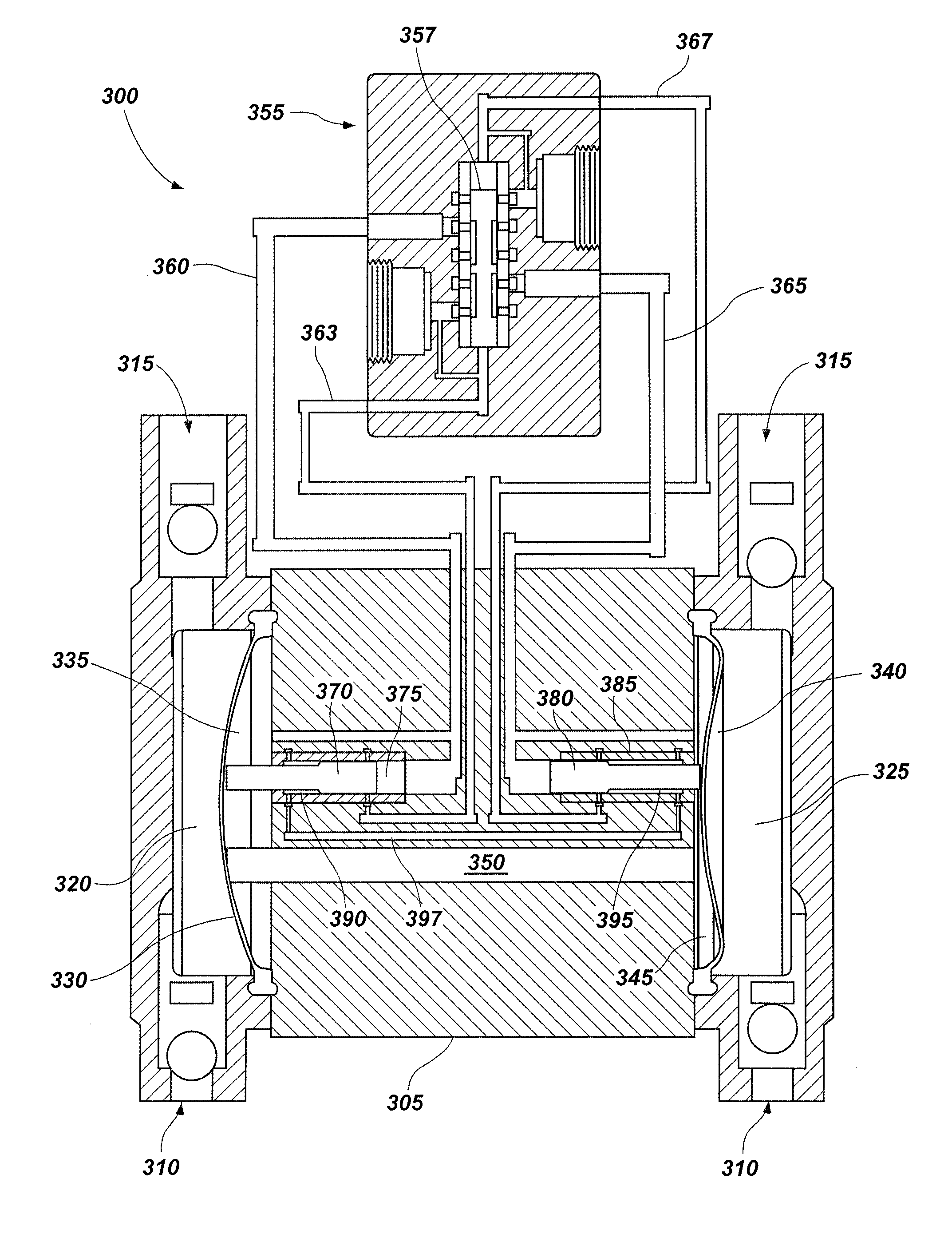
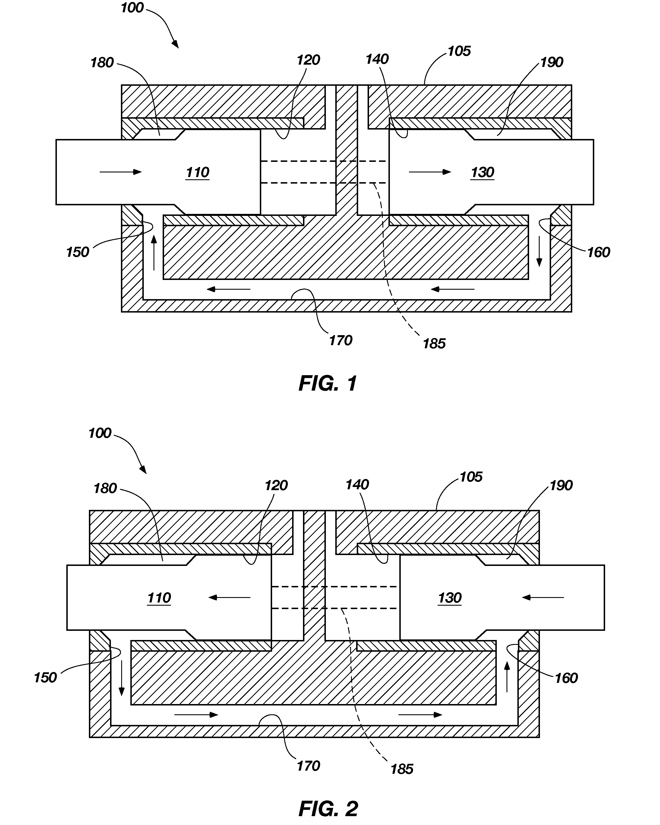
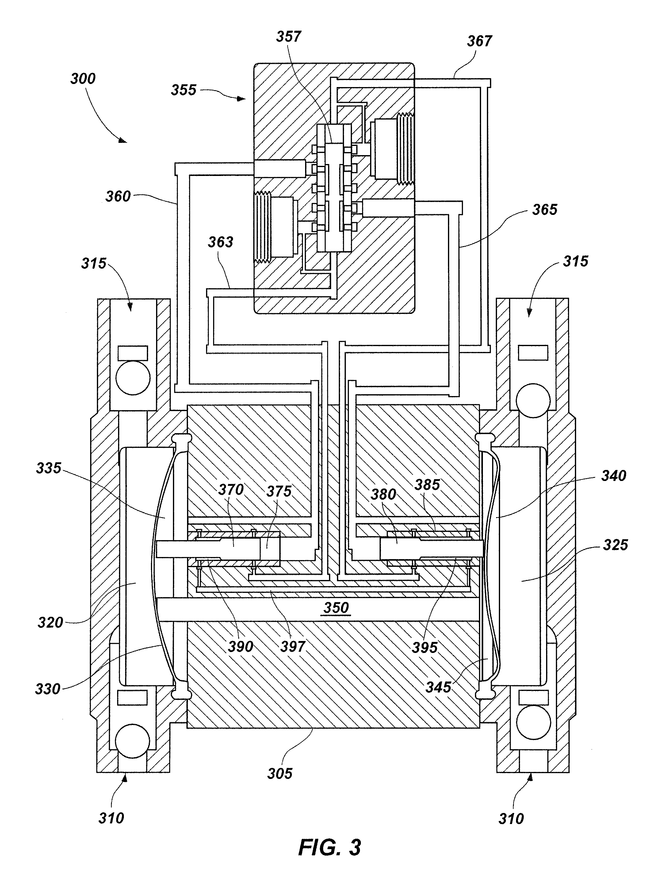
[0017]Various embodiments of the present invention comprise piston systems comprising a closed-loop flow path. Referring to FIG. 1, a piston system 100 may comprise a housing 105 at least substantially enclosing a first piston 110 disposed within a first piston chamber 120 and a second piston 130 disposed within a second piston chamber 140. In at least some embodiments, the housing 105 may comprise at least a portion of a reciprocating pump assembly, and, as noted above, may not comprise a single component. The piston system 100 is configured so that the first piston 110 and second piston 130 move in relation to each other. For example, when the first piston 110 is displace...


PUM


Abstract

Piston systems comprise a housing including a first piston chamber and a second piston chamber therein. A first piston is movably disposed within the first piston chamber and a second piston is movably disposed within the second piston chamber. A flow path extends between and couples the first piston chamber and the second piston chamber. Reciprocating pumps comprising a flow path between a plurality of piston chambers and methods of driving reciprocating pumps are also disclosed.

Description

TECHNICAL FIELD[0001]The present invention relates generally to piston systems. More particularly, embodiments of the present invention relate to piston systems having a closed-loop flow path between two or more piston chambers, pumps including such structures, and methods of driving pumps.BACKGROUND[0002]Numerous industries and many applications utilize reciprocating pumps for transporting fluids. For example, reciprocating pumps are found in industries such as shipping, processing, manufacturing, irrigation, gasoline supply, air conditioning systems, flood control, marine services, etc. Conventional reciprocating pumps may employ one or more piston systems comprised of a plurality of pistons and associated piston chambers in driving the pump. Conventionally, as pistons displace longitudinally within the piston chamber, one or more volumes between the piston and the piston chamber increase or decrease, depending on the direction of longitudinal displacement. The increasing volumes ...

Claims


Application Information

Patent Timeline
Patent Type & Authority Applications(United States)
IPC IPC(8): F04B27/00F01B1/00
CPCF04B27/005F04B45/043F04B43/026
Inventor SIMMONS, TOM M.SIMMONS, JOHN M.SIMMONS, DAVID M.
Owner GRACO FLUID HANDLING A
Why Eureka
Try Eureka