Fixation device for proximal humerus fractures

a humerus and fixation device technology, applied in the field of surgical plates, can solve the problems of reducing the range of motion and achieving unsuccessful outcomes, and achieve the effect of enhancing columnation support and preventing varus collapse of the humerus

Active Publication Date: 2015-11-05
WRIGHT MEDICAL TECH +1
View PDF3 Cites 46 Cited by
  • Summary
  • Abstract
  • Description
  • Claims
  • Application Information

AI Technical Summary

Benefits of technology

[0005]The herein described fixation device allows for fixation of proximal humerus fractures and prevents varus collapse of the humerus during rehabilitation. Generally, the apparatus includes a humerus plate that that includes two groups of apertures in the proximal portion of the fixation device. One group receives fasteners to secure an upper portion of the plate to the humeral head and another group receives fasteners that transcend the surgical neck and lateral inferior portion of said humeral head and penetrate the calcar region of the humerus. The fasteners are sized so that the

Problems solved by technology

It is important to prevent such collapse because it can alter the biomechanics of

Method used


Image

  • Fixation device for proximal humerus fractures
  • Fixation device for proximal humerus fractures
  • Fixation device for proximal humerus fractures

Examples


second embodiment

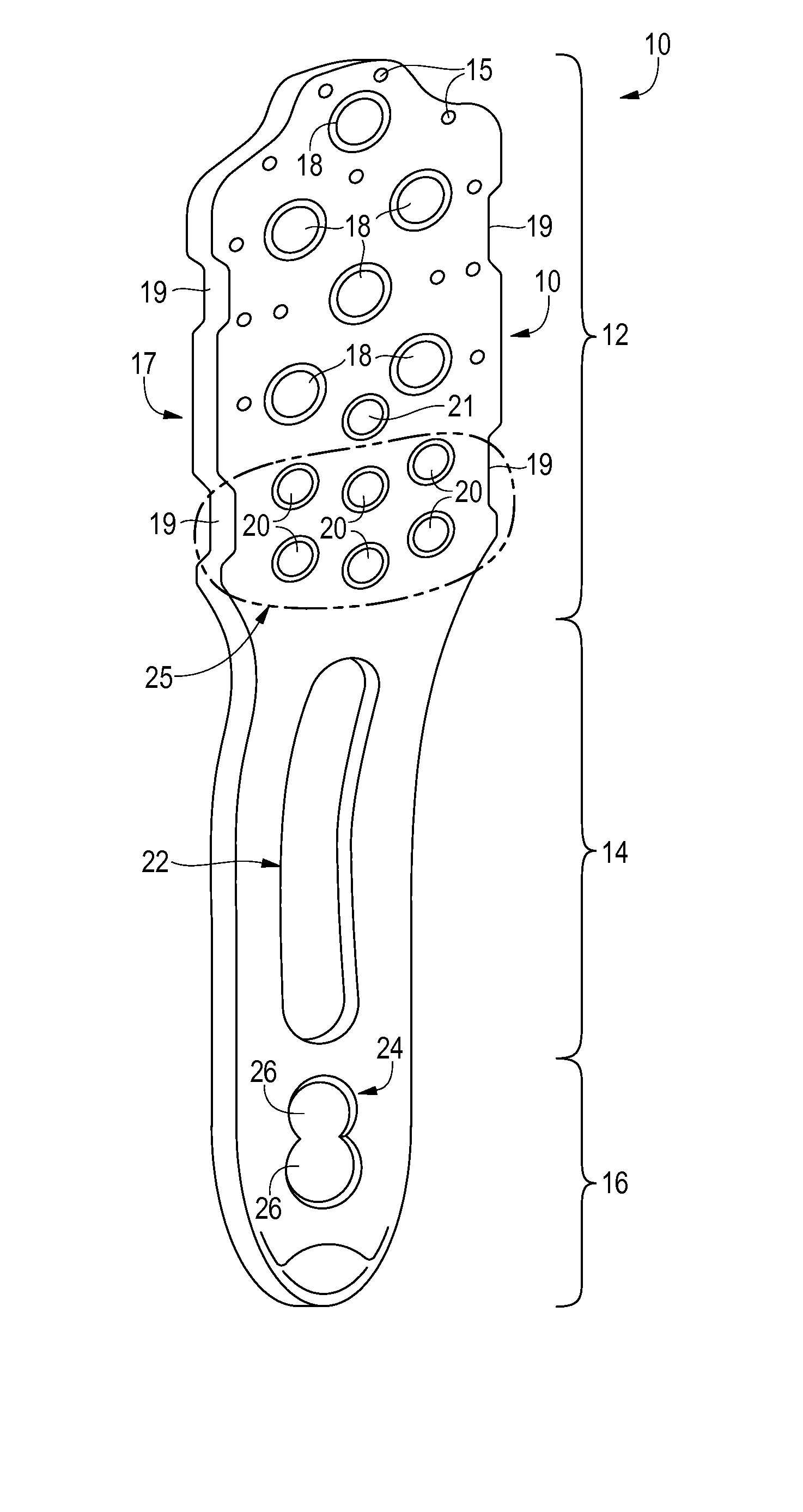
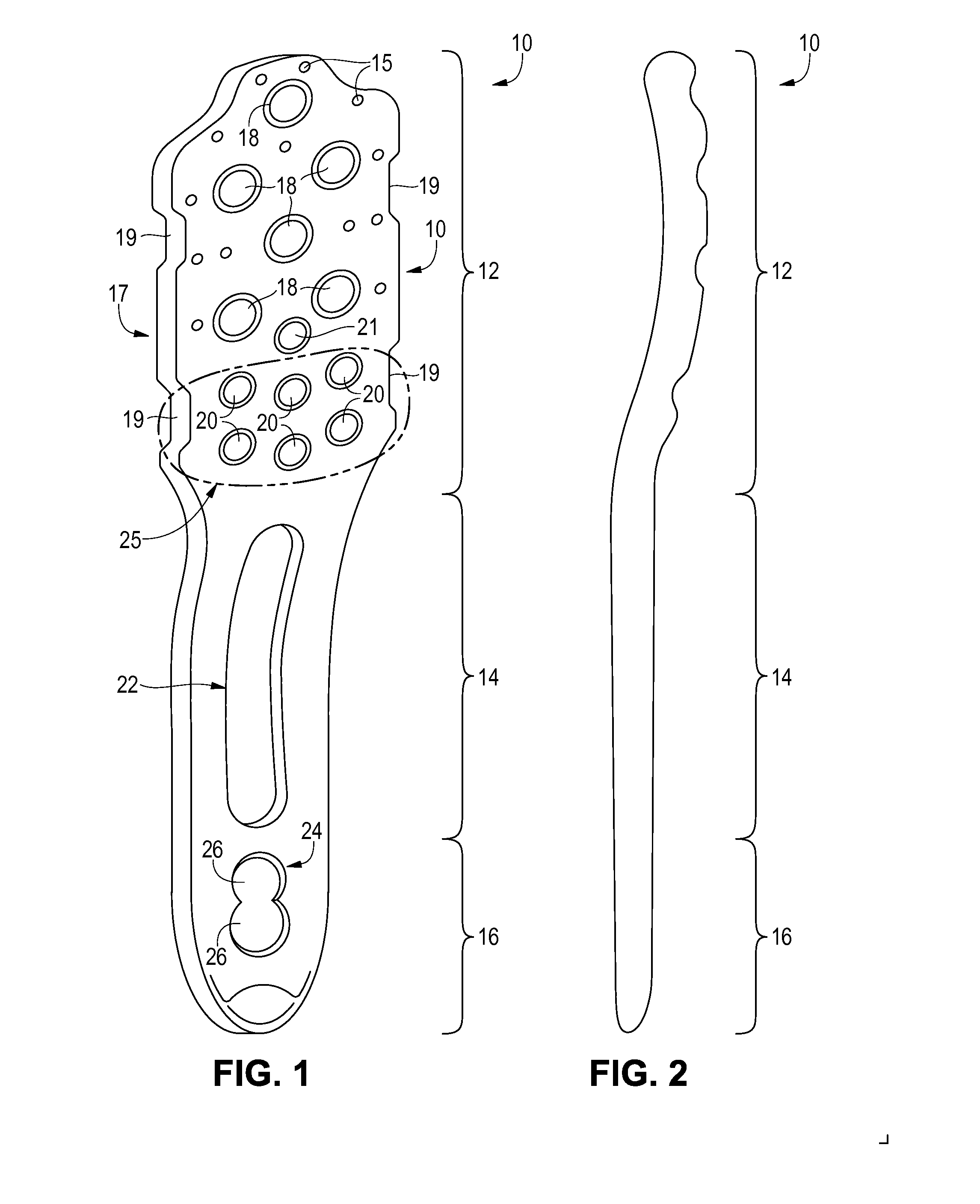
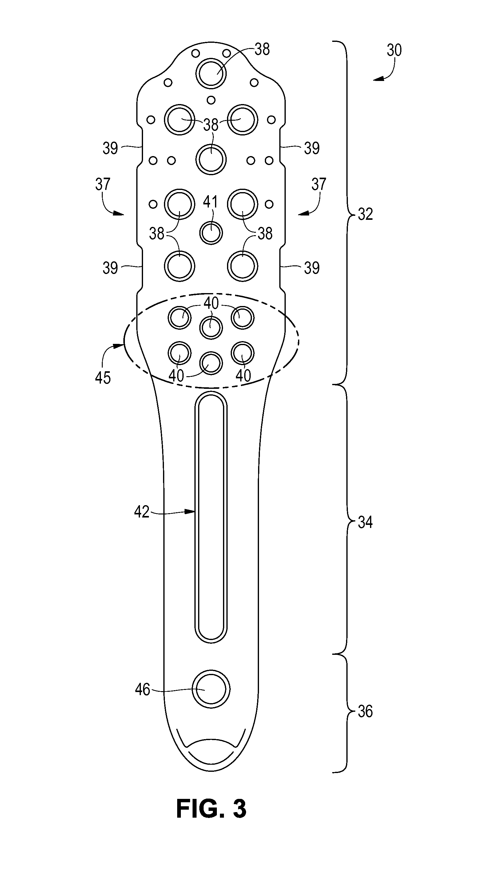
[0020]FIG. 3 illustrates an implantable humerus plate 30 that can be used to secure bone fragments of the proximal humerus together. As is apparent from this figure, the humerus plate 30 is very similar to the humerus plate 10 shown in FIG. 1. Accordingly, the humerus plate 30 can be unitarily formed from a single piece of generally flat material and can generally comprise a proximal portion 32, a central portion 34, and a distal portion 36. The proximal portion 32 can have a gentle curvature that is adapted to match the curvature of the head of the humerus bone. As with the humerus plate 10, the humerus plate 30 can be approximately 80 to 100 mm long and approximately 2 to 5 mm thick.

[0021]The proximal portion 32 of the humerus plate 30 is wider than the central and distal portions 34, 36 of the plate. In some embodiments, the proximal portion 32 is approximately 18 to 20 mm wide and the central and distal portions 34, 36 are approximately 10 to 14 mm wide. As is further shown in F...

embodiment 210

[0029]Referring to FIG. 6 and the larger form 220 of embodiment 210, the same humerus structures are shown as in FIG. 4 with the same goal to penetrate the calcar region 55 in order to prevent varus collapse as described above for FIG. 4. However, the screw arrangement for the embodiment shown in FIG. 6 is different. Proximal screws 254 pass through openings 238 into the humeral head 53 as in the embodiment in FIG. 4, however screws 255a and 255b pass through openings 241 and slant downward penetrating into calcar region 55 from above. Preferably, screws 255a and 255b angle towards each other slightly so that their tips will both penetrate into calcar region 55 at or above the concave area 59 while compressing the humeral head from slightly different angles. Smaller screws 254b pass through openings 241a and are angled slightly upwards to penetrate into humeral head 53 providing a cross compressive force with screws 255a,b.

[0030]Calcar screws 256a,b pass through openings 240 and ex...


PUM


Abstract

A fixation device is disclosed for the fixation of proximal humerus fractures includes an implantable humerus plate having a proximal portion adapted to be positioned at a head and medial calcar of the humerus, a distal portion adapted to be positioned along a shaft of the humerus, and a plurality of calcar openings provided through the proximal portion adapted to receive calcar fasteners that extend into the medial calcar. The calcar fasteners are grouped into a rafted configuration and the tips of each fastener are positioned into the calcar region so that torsional forces bearing upon the calcar regions are distributed into the rafted fastener support, thereby avoiding varus collapse of the humerus head after fixation of the fracture.

Description

[0001]This application claims the benefit of filing priority under 35 U.S.C. §119 and 37 C.F.R. § 1.78 of PCT Application Serial No. PCT / US2014 / 011113 filed Jan. 10, 2014, for an APPARATUS FOR THE FIXATION OF PROXIMAL HUMERUS FRACTURES which in turn claims priority to expired U.S. Provisional Application Ser. No. 61 / 751,485, filed Jan. 11, 2013, for a CALCAR OSTEOSYNTHESIS FOR PROXIMAL HUMERUS FRACTURES. All information disclosed in those prior applications are incorporated herein by referenceFIELD OF THE INVENTION[0002]The present invention relates generally to surgical plates for the mending of broken bones in the human body. In particular, the present invention relates to fixation plates for the upper arm or humerus. In even further detail, the present invention relates to fixation plate strategies to avoid varus collapse of the humerus head.BACKGROUND OF THE INVENTION[0003]When a proximal humerus fracture occurs, it is sometimes necessary to fix the bone fragments together to en...

Claims


Application Information

Patent Timeline
IPC IPC(8): A61B17/80
CPCA61B17/8061A61B17/809A61B17/1739A61B17/8042A61B17/8866A61B17/1778A61B17/8019
Inventor PONCE, BRENT A.WHITCOMB, JOHN
Owner WRIGHT MEDICAL TECH
Why Eureka
Try Eureka