Wall for receiving wear plates and method for replacing wear plates

a technology for receiving wear plates and receiving walls, which is applied in the direction of chutes, manufacturing tools, transportation and packaging, etc., can solve the problems of high frictional stress on the surface of the machine that is in contact with these bulk materials, easy replacement, and the possibility of damage to the cover, etc., and achieves cost-effective effects

Active Publication Date: 2015-11-26
TAKRAF
View PDF7 Cites 1 Cited by
  • Summary
  • Abstract
  • Description
  • Claims
  • Application Information

AI Technical Summary

Benefits of technology

[0011]The present invention pertains to a design for accomplishing an object of the invention for a wall, which makes it possible to replace wear p...

Problems solved by technology

When loading and unloading bulk materials, especially coarse-grained or lumpy bulk materials, the surfaces of the machines that are in contact with these bulk materials are subject to especially intense frictional stress.
However, the edges and snap-in elements may become damaged when dumping in rocky material, which makes easy replacement impossible.
However, the cover may be expected to become damaged when filling rocky materials.
Since it is difficult to access these fastening elements and they may also be destroyed because of the mechanically rubbed-off particles and the contamination of these fastening elements, all the means disclosed for accomplishing the object have a pr...

Method used


Image

  • Wall for receiving wear plates and method for replacing wear plates
  • Wall for receiving wear plates and method for replacing wear plates
  • Wall for receiving wear plates and method for replacing wear plates

Examples


Embodiment Construction

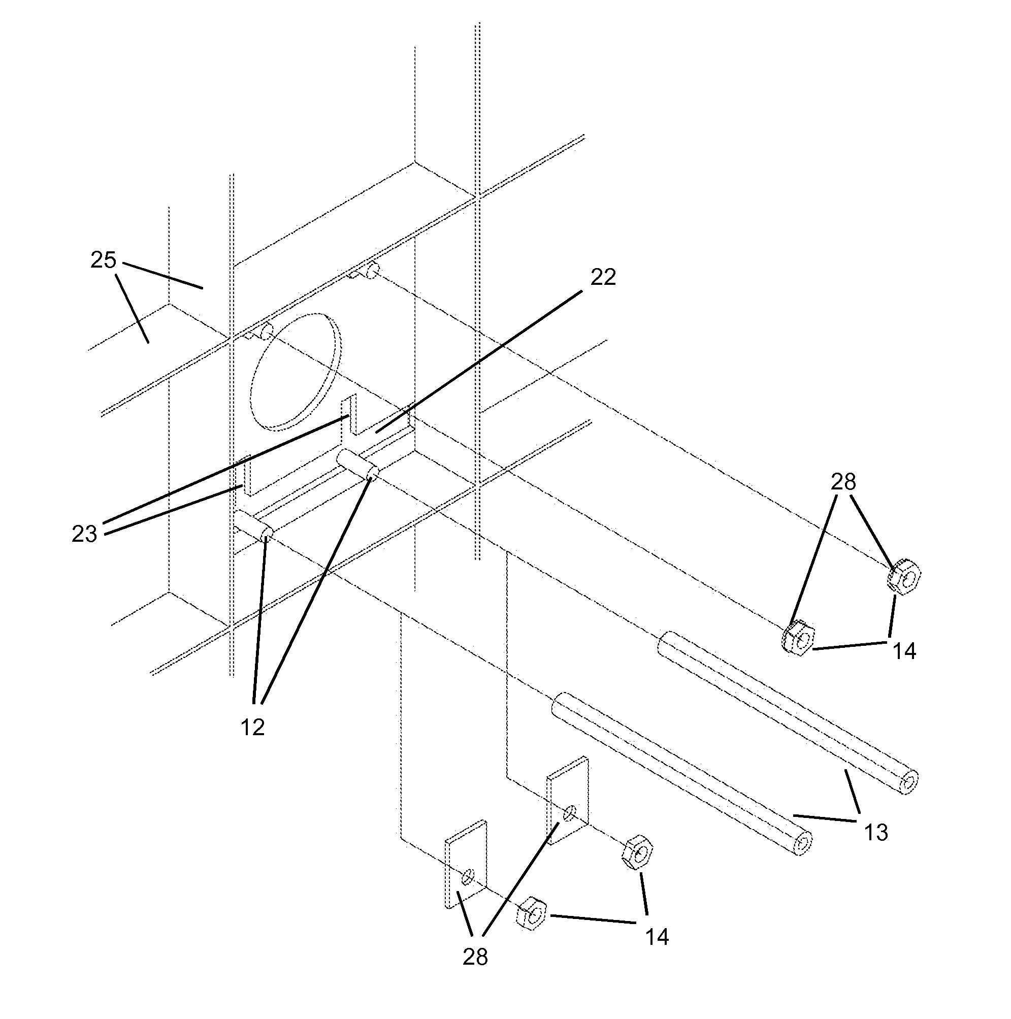
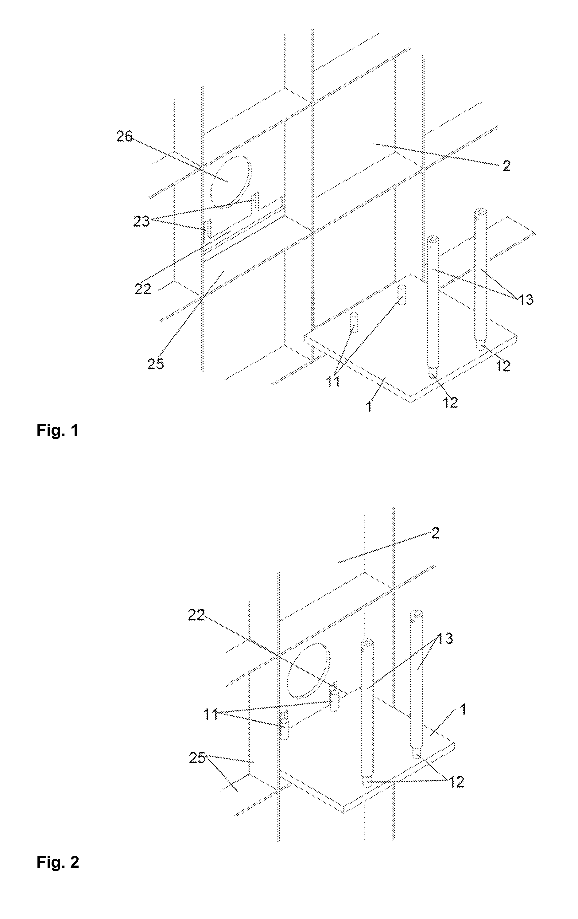
[0043]Referring to the drawings, FIG. 1 shows a wear plate (1). The wear plate (1) is square (edge length 30 cm). FIG. 2 shows the wear plate tilted horizontally and the fastening elements (11) located far from the gap in the front, inserted into the gap (22). The fastening elements (11) located far from the gap now pass through the slots (23) intended for them.

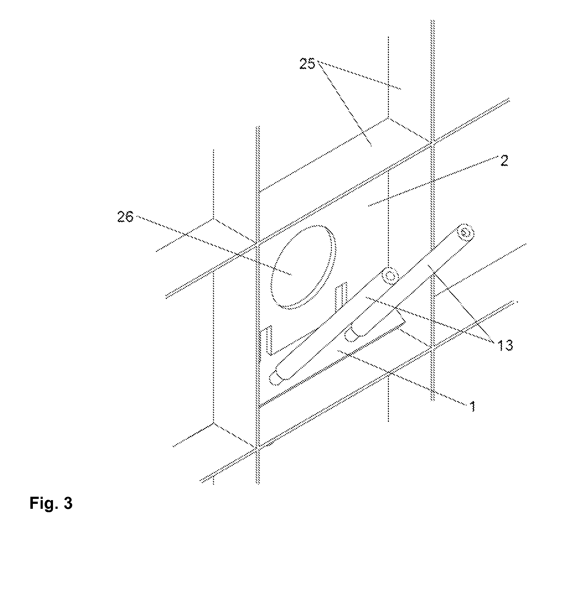
[0044]In FIG. 3, the fastening elements (11) have already passed through the slots (23) and the wear plate (1) is tilted now in the gap (22) and using the insertion ids (13), which are passed farther through the gap (22), and the fastening elements (12) located close to the gap are inserted into the slots (22) and the fastening elements (11) located far from the gap (not shown here) are inserted into the openings for mounting the fastening elements located far from the gap. An additional round opening (26), through which a tight wear plate (1) can be loosened by means of blows with a hammer, is provided centrally to the faste...


PUM

PropertyMeasurementUnit
Thicknessaaaaaaaaaa
Widthaaaaaaaaaa

Abstract

A wall (2), for receiving one or more wear plates (1), has openings for receiving at least some of the fastening elements (11, 12) of the wear plates (1). The wall has, furthermore, gaps (22), with dimensions corresponding to the width and thickness of the wear plates (1). Slots (23) extend from the gaps (22). The slots (23) correspond to the fastening elements (11, 12) of the wear plate (1). The fastening elements (11, 12) of the wear plates (1) can pass through the wall (2), through the slots (23).

Description

CROSS REFERENCE TO RELATED APPLICATIONS[0001]This application claims the benefit of priority under 35 U.S.C. §119 of German Patent Application DE 10 2014 209 697.9 filed May 21, 2014, the entire contents of which are incorporated herein by reference.FIELD OF THE INVENTION[0002]The present invention relates to a wall for receiving one or more wear plates, wherein this wall has openings for receiving at least some of the fastening elements of the wear plates.BACKGROUND OF THE INVENTION[0003]When loading and unloading bulk materials, especially coarse-grained or lumpy bulk materials, the surfaces of the machines that are in contact with these bulk materials are subject to especially intense frictional stress. These surfaces are therefore frequently protected with protective surfaces, so-called wear plates, against the stress.[0004]A plurality of linings of dumping or transportation devices subject to abrasive stress are known from the state of the art.[0005]Thus, U.S. Pat. No. 6,279,71...

Claims


Application Information

Patent Timeline
IPC IPC(8): B65G11/02B65G11/20B65G11/18
CPCB65G11/02Y10T29/49897B65G11/20B65G11/18B65G11/166B65G2201/04B65G2207/48
Inventor KAHRGER, RAINERDILEFELD, MARIOLLANOS, CARLOS
Owner TAKRAF
Why Eureka
Try Eureka