X-ray radiation generator

a radiation generator and generator technology, applied in the direction of x-ray tubes, electrical equipment, electric discharge tubes, etc., can solve the problems of high production cost, and difficult heat transmission between the anode and the heat sink

Active Publication Date: 2017-11-23
SMITHS HEIMANN
View PDF3 Cites 5 Cited by
  • Summary
  • Abstract
  • Description
  • Claims
  • Application Information

AI Technical Summary

Benefits of technology

[0008]The object of the invention is to propose an X-ray tube, in particular a vacuum X-ray tube, with an anode that conducts a high voltage, preferably greater than 120 kV, particularly preferably greater than 300 kV, and heats up during operation, in which the insulation breakdown resistance of the anode, which is operated with higher voltages, relative to the surroundings is improved.

Problems solved by technology

A heat sink composed of ceramic, however, is expensive to produce since special molds must be used.
This makes the heat transmission between the anode and the heat sink problematic: on the one hand, the heat sink should have the best possible heat conduction contact with the anode in order to achieve the highest possible heat transfer coefficient.

Method used


Image

  • X-ray radiation generator
  • X-ray radiation generator
  • X-ray radiation generator

Examples


Embodiment Construction

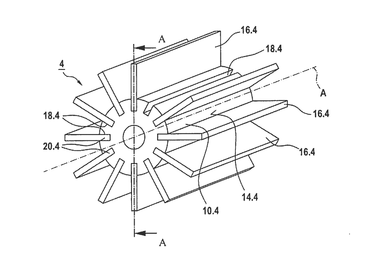
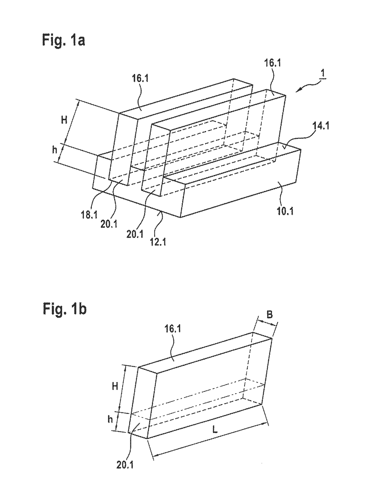
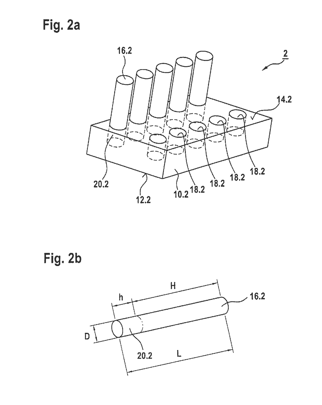
[0031]Other advantages, features, and details of the invention ensue from the following description, in which exemplary embodiments of the invention are described in detail with reference to the drawings. The features mentioned in the claims and in the description can each be essential to the invention by themselves or in any combination with one another. Likewise, the features mentioned above and explained in greater detail below can be used by themselves or in any combination with one another. Parts or components that are functionally similar or identical are sometimes provided with the same reference numerals. The terms “left,”“right,”“above,” and “below” used in the description of the exemplary embodiments refer to the drawings in a direction with normally legible figure number and normally legible reference numerals. The embodiments depicted and described are not to be taken as comprehensive and instead, have an exemplary character intended for explanation of the invention. The...


PUM

PropertyMeasurementUnit
thermal conductivity coefficientaaaaaaaaaa

Abstract

The present invention relates to an X-ray tube (30) with an anode (36) that conducts a high voltage, preferably greater than 120 kV, particularly preferably greater than 300 kV, and heats up during operation, wherein the anode is connected in a thermally conductive way to a heat sink (4), which has a base body (10.4) composed of a metal with a heat absorbing surface (12.4) for coupling to the anode (36) as a heat source (36) and a heat dissipating surface (14.4) that is enlarged by means of heat dissipating elements (16.4) that are connected to the base body (10.4), wherein the heat dissipating elements (16.4) are composed of an electrically insulating material having a thermal conductivity on the same order of magnitude as that of the metal of the base body (10.4), and wherein the heat dissipating elements (16.4) have a height (H) starting from the base body (10.4) of the heat sink (4) so that taking into account the high voltage and an insulating medium surrounding the heat dissipating elements (16.4), there is a sufficient insulation breakdown resistance relative to the surroundings of the X-ray tube (30).

Description

[0001]In general, the present invention relates to an X-ray tube with an anode that conducts a high voltage, preferably greater than 120 kV, particularly preferably greater than 300 kV, and heats up during operation. In particular, the invention relates to an X-ray tube with a heat sink, which is suitable for cooling the high voltage-conducting anode in cases where space is limited.BACKGROUND OF THE INVENTION[0002]X-ray tubes are known as an example of an X-ray radiation generator. To avoid voltage flashovers, it is necessary to insulate high voltage-conducting parts such as anodes from other parts in the vicinity by providing sufficient insulation.[0003]For example, in order to increase insulation breakdown resistance, DD 139 327 A proposes that a housing of an X-ray tube additionally have a sleeve built into it, which is composed of a dielectric material such as epoxy resin with quartz flour, ceramic, or PTFE, which essentially contains a bulb of the X-ray tube inserted therein an...

Claims


Application Information

Patent Timeline
Patent Type & Authority Applications(United States)
IPC IPC(8): H01J35/12
CPCH01J2235/1295H01J35/12H01J2235/1283
Inventor HESS, GREGORLENZ, KAIHIRT, MICHAELADAM, ALEXANDERSTREYL, ANDREAS
Owner SMITHS HEIMANN
Why Eureka
Try Eureka