Safety sheath for hypodermic syringe needle

a safety sheath and hypodermic syringe technology, applied in the direction of intravenous devices, infusion needles, other medical devices, etc., can solve the problems of unavoidable fact, increased cost of retrofitting or remolding conventional injecting apparatuses, and obsolete original manufacturing molds, so as to facilitate the subsequent sleeving process, prevent accidental jabs or pricks, and enhance the tightness of latches

Inactive Publication Date: 2012-01-26
WU KUO CHENG
View PDF4 Cites 4 Cited by
  • Summary
  • Abstract
  • Description
  • Claims
  • Application Information

AI Technical Summary

Benefits of technology

[0016]The primary object of the present invention is to provide a safety sheath for hypodermic syringe needle with basic structure comprising a proximal mounting ring, a distal mounting ring and a shielding sheath, wherein the proximal mounting ring, which sleeving over the bottom peripheral of the hypodermic syringe, has a proximal annular groove created on the circumferential surface; the distal mounting ring, which sleeving over the top peripheral of the hypodermic syringe, includes a conical frustum surface formed in the bottom section, an annular stopping curb formed in the top section and a distal annular groove created in the middle section thereof; and the shielding sheath, which sleeving over the peripheral walls of the proximal mounting ring and distal mounting ring, includes an inward annular fillet, a pair of symmetrical slits in diametrically opposed fashion, and a pair of symmetrical tensional recesses in diametrically opposed fashion, wherein the inward annular fillet is bisected into two symmetrical curved segments by the pair symmetrical slits such that the thickness of each curved segment is non-uniform like crescent; each of both tensional recesses is respectively located at symmetrical side in diametrically opposed fashion; and each slit is upwardly and longitudinally cut at the lower section of the circumferential wall; by means of the pair symmetrical slits, the lower section of the circumferential wall is bisected into two symmetrical semicircular aprons. During assembling process, both symmetrical semicircular aprons in the circumferential wall are outwardly hauled by two outwards forces such that the bore profile of the bottom face is dilated and deformed from original circular shape into oval shape, meanwhile the bore profile of the inward annular fillet is dilated into circular shape. Accordingly, both of the dilated oval bore profile of the bottom face and dilated circular bore profile of the inward annular fillet will not only facilitate subsequent sleeving process but also enhance the tightness for the latch of the shielding sheath with the distal mounting ring so that the medical personnel can prevent from accidental jabs or pricks by the hypodermic needle.
[0017]The other object of the present invention is to provide a safety sheath for hypodermic syringe needle with basic structure comprising a proximal mounting ring, a distal mounting ring and a shielding sheath as aforesaid, wherein each root of both bisected symmetrical semicircular aprons in the circumferential wall is terminated by each tensional recess, which not only absorbs the stress caused by outwards forces but also boosts recovering resilience for releasing deformation to ensure deformed bottom face of the shielding sheath is recovered to original shape without distortion.

Problems solved by technology

For medical personnel, having been inadvertently pricked by the hypodermic needle in handling hypodermic syringe becomes an unavoidable fact.
However, some drawbacks in the foregoing various types of “jacketed safety hypodermic injection apparatus” cause related manufacturers reluctant to market.
Because the modified conventional hypodermic injection apparatus, whose hypodermic syringe 1 is adapted to include a distal circumferential groove 1a and a proximal circumferential groove 1b, an extra cost will be incurred for retrofitting or remolding conventional injecting apparatus as original manufacturing molds will be obsolete.
However, there is serious assembly drawback in such kind of structure as below.
From foregoing description, the assembling process of the needle guard 4 and collar 3 on the hypodermic syringe 5 is indeed very complicated and difficult.
Therefore, the shielded needle of U.S. Pat. No. 4,631,057 is not suitably applied in current mass production of the “safety hypodermic injection apparatus” either.
In conclusion the drawback description for two US patents as typical conventional injection apparatus of prior arts heretofore, the substantial factor in hindering the “jacketed safety hypodermic injection apparatus” into mass production and marketing promotion is bad structural design.
Other than such bad structural design, current laws do not have compulsory regulations to require that manufacturer of the “safety hypodermic injection apparatus” is obligatory to retrofit existing conventional injection apparatus with drawback(s) mentioned above.
Consequently, most manufacturers of the conventional injection apparatus are unwilling to invest or transform into production of “safety hypodermic injection apparatus”.
Therefore, medical personnel and medical waste handling personnel are inevitable to continually stay under the menace of being possibly pricked by the hypodermic needle accidentally.

Method used


Image

  • Safety sheath for hypodermic syringe needle
  • Safety sheath for hypodermic syringe needle
  • Safety sheath for hypodermic syringe needle

Examples


Embodiment Construction

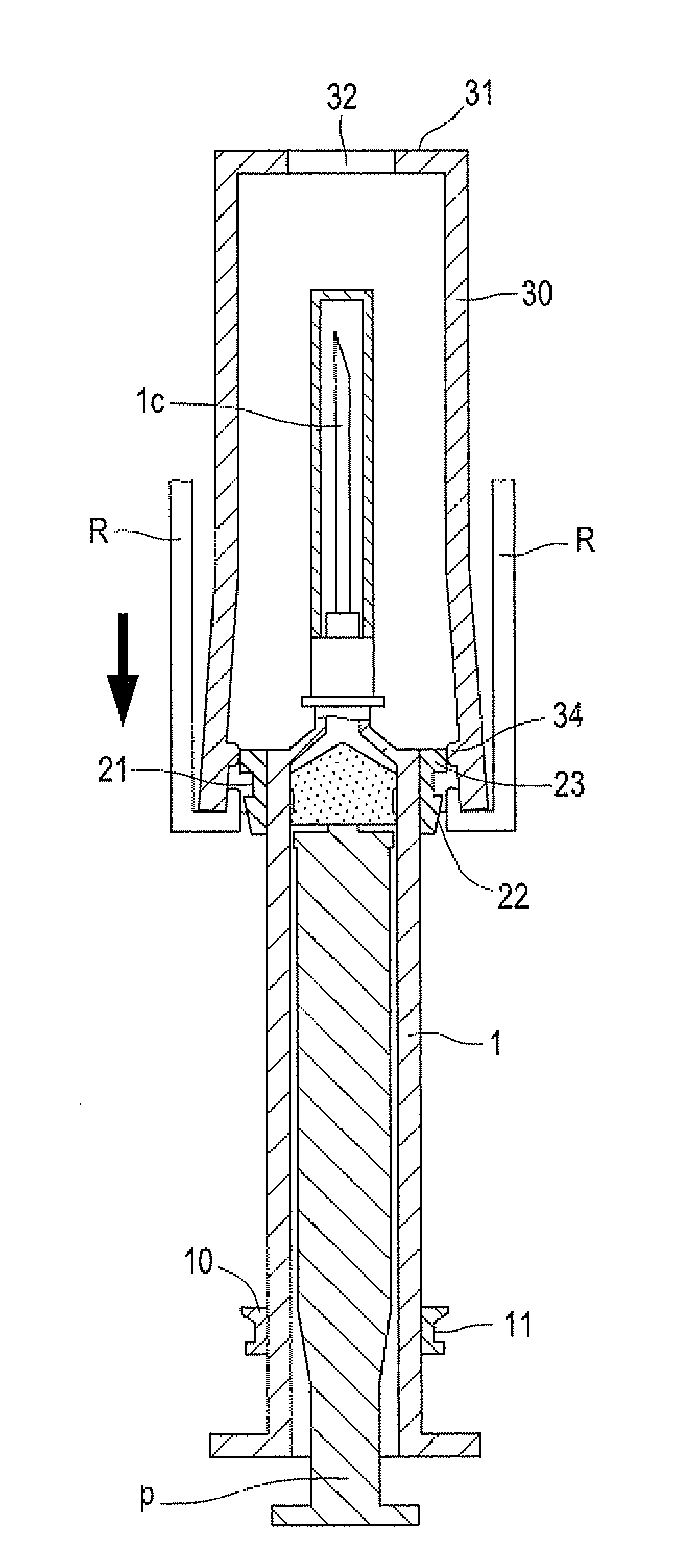
[0054]Please refer to FIGS. 13 through 18. Other than a conventional hypodermic injection apparatus, which includes a hypodermic syringe 1 with a pair of finger resting wings, a hypodermic needle 1c with a needle cap and a piston or plunger P with a thumb rest, the basic structure of a safety sheath for hypodermic syringe needle according to a first preferred embodiment of the present invention comprises a proximal mounting ring 10, a distal mounting ring 20 and a shielding sheath 30.

[0055]Referring to FIGS. 13 to 18, the proximal mounting ring 10 is a transparent or translucent hollow circular element with inner diameter equaling to outer diameter of the hypodermic syringe 1 so that it circumjacently sleeves over the bottom peripheral of the hypodermic syringe 1 in tight manner, has a proximal annular groove 11 created on the circumferential surface;

[0056]The distal mounting ring 20 is a transparent or translucent hollow circular element with inner diameter equaling to outer diamet...


PUM


Abstract

The present invention provides a safety sheath for hypodermic syringe needle comprising a proximal mounting ring, a distal mounting ring and a shielding sheath. The shielding sheath includes two symmetrical slits, two symmetrical semicircular aprons and an inward annular fillet, which is bisected into two symmetrical curved segments with crescent thickness, namely marginal thickness is less than central thickness. During sleeving the shielding sheath over the distal mounting ring and proximal mounting ring, both symmetrical semicircular aprons are outwardly hauled by outwards forces such that the bore profile of the inward annular fillet is dilated into circular shape, which will not only facilitate subsequent sleeving process without difficulty but also enhance the tightness for the latch of the shielding sheath with the distal mounting ring in locked manner without any possibility of mutually slipping displacement so that medical personnel in handling can prevent from accidental pricks by hypodermic needle.

Description

FIELD OF THE PRESENT INVENTION[0001]The present invention relates to a safety sheath for hypodermic syringe needle, particularly for one to be used in a “jacketed safety hypodermic injection apparatus”. It provides a convenient mechanism for easily being introduced into automatic mass production without replacement of the existing machinery or equipments. Therefore, the intention of investing or transforming into production of “safety hypodermic injection apparatus” for the manufacturers of the conventional injection apparatus will be encouraged and spurred. Thus, medical personnel and medical waste handling personnel can be early freed from the menace of being possibly pricked by the hypodermic needle accidentally.BACKGROUND OF THE INVENTION[0002]For medical personnel, having been inadvertently pricked by the hypodermic needle in handling hypodermic syringe becomes an unavoidable fact. According to report from USA Center for Disease Control and Prevention (CDC) that annual consumpt...

Claims


Application Information

Patent Timeline
Patent Type & Authority Applications(United States)
IPC IPC(8): A61M5/32
CPCA61M5/3243A61M2005/3247A61M2207/00
Inventor WU, KUO CHENG
Owner WU KUO CHENG
Why Eureka
Try Eureka