System and method for safe switching in an ac-to-ac converter

a technology of ac-to-ac converter and a safe switching, which is applied in the direction of electric variable regulation, process and machine control, instruments, etc., can solve the problems of inability to turn off in dynamic mode, unable to provide precise current control, and motor drives that incorporate igbts are typically significantly more expensive than soft starters, so as to prevent a voltage spike

Active Publication Date: 2015-12-03
EATON INTELLIGENT POWER LIMITED
View PDF4 Cites 0 Cited by
  • Summary
  • Abstract
  • Description
  • Claims
  • Application Information

AI Technical Summary

Benefits of technology

[0008]The present invention provides a system and method for controlling switching in an IGBT-based AC-AC converter to avoid voltage spikes during switching pattern transitions in the event of an erroneous current sign reading or identification.
[0009]In accordance with one aspect of the invention, a controller for an AC-AC converter to control current flows from an AC source to an AC load is programmed to determine a direction of current flow on each of one or more supply lines that provide AC power to the AC-AC converter, each supply line corresponding to a phase in the AC load. The controller is also programmed to determine a switching pattern for each of a plurality of line-side switches and each of a plurality of floating-neutral side switches in the AC-AC converter based on the determined direction of current flow on each of the supply lines and cause each of the plurality of line-side switches and each of the plurality of floating-neutral side switches to operate in either an ON condition or an OFF condition according to the determined switching pattern, such that a controlled current flow is output from the AC-AC converter. The controller is further programmed to implement a safe-switching routine when transitioning from a first switching pattern to a second switching pattern, the safe-switching routine preventing a non-zero current from being interrupted during the transitioning from the first switching pattern to the second switching pattern.
[0010]In accordance with another aspect of the invention, a load control device to control current flow to an AC load includes a circuit having an input connectable to a line terminal of an AC source, an output connectable to a load terminal of an AC load, one or more supply lines each corresponding to a phase in the AC load and connecting the input and output to transmit power from the AC source to the AC load, a plurality of line-side switches connected between the line terminals and the load terminals such that each supply line includes at least one line-side switch connected thereto, and a plurality of floating-neutral side switches connected to the load terminal at one end and together at a common connection at another end, such that each supply line includes at least one floating-neutral side switch connected thereto. The load control device also includes a controller connected to the circuit and programmed to implement a switching pattern for each of the plurality of line-side switches and each of the plurality of floating-neutral side switches based on a determined direction of current flow on each of the supply lines and transition between switching patterns responsive to a changing direction of current flow on a supply line. In transitioning between switching patterns, the controller is further programmed to establish a transition window and implement a transition switching pattern for each of the plurality of line-side switches and each of the plurality of floating-neutral side switches for a duration of the transition window, to prevent a voltage spike from occurring.

Problems solved by technology

While SCRs can be turned on at will, they cannot be turned off in a dynamic and controllable fashion, as SCRs turn off naturally when the current reaches zero.
SCRs thus lack the desired capability to provide precise control over current—with more control over the current being desirable in order to reduce harmonics, reduce heat dissipation, and further improve AC motor starting, restarting, and stopping characteristics.
However, such use of IGBTs is often restricted to complex “motor drives,” and while the use of IGBTs in motor drives works very well, the motor drives that incorporate the IGBTs are typically significantly more expensive than a soft starter.
While certain elements in the motor drive can be avoided / eliminated in an attempt to reduce cost, such as avoiding usage of a DC link by using a matrix configuration, such converters use many more devices and are also costly.
As such, in the end, AC choppers require large passive elements such as capacitors, thus incurring a high cost.
It is recognized, however, that—as the switching logic is predicated on having perfect knowledge of the direction / sign of the current in all phases—issues can arise when any of the phase currents traverse zero (i.e., zero crossing) and a transitioning from one switching pattern to another switching pattern is implemented.
That is, in some cases, because of noise for instance, the system may believe that some current is negative while in fact it is positive, or vice-versa, and an erroneous current reading may lead to switching the IGBTs in a wrong manner.
In some cases, no harm may result from an incorrect switching pattern, but in other cases an incorrect switching pattern may result in current in one phase being interrupted, thereby creating a voltage spike because of the largely inductive nature of the machine windings.

Method used


Image

  • System and method for safe switching in an ac-to-ac converter
  • System and method for safe switching in an ac-to-ac converter
  • System and method for safe switching in an ac-to-ac converter

Examples


example 1

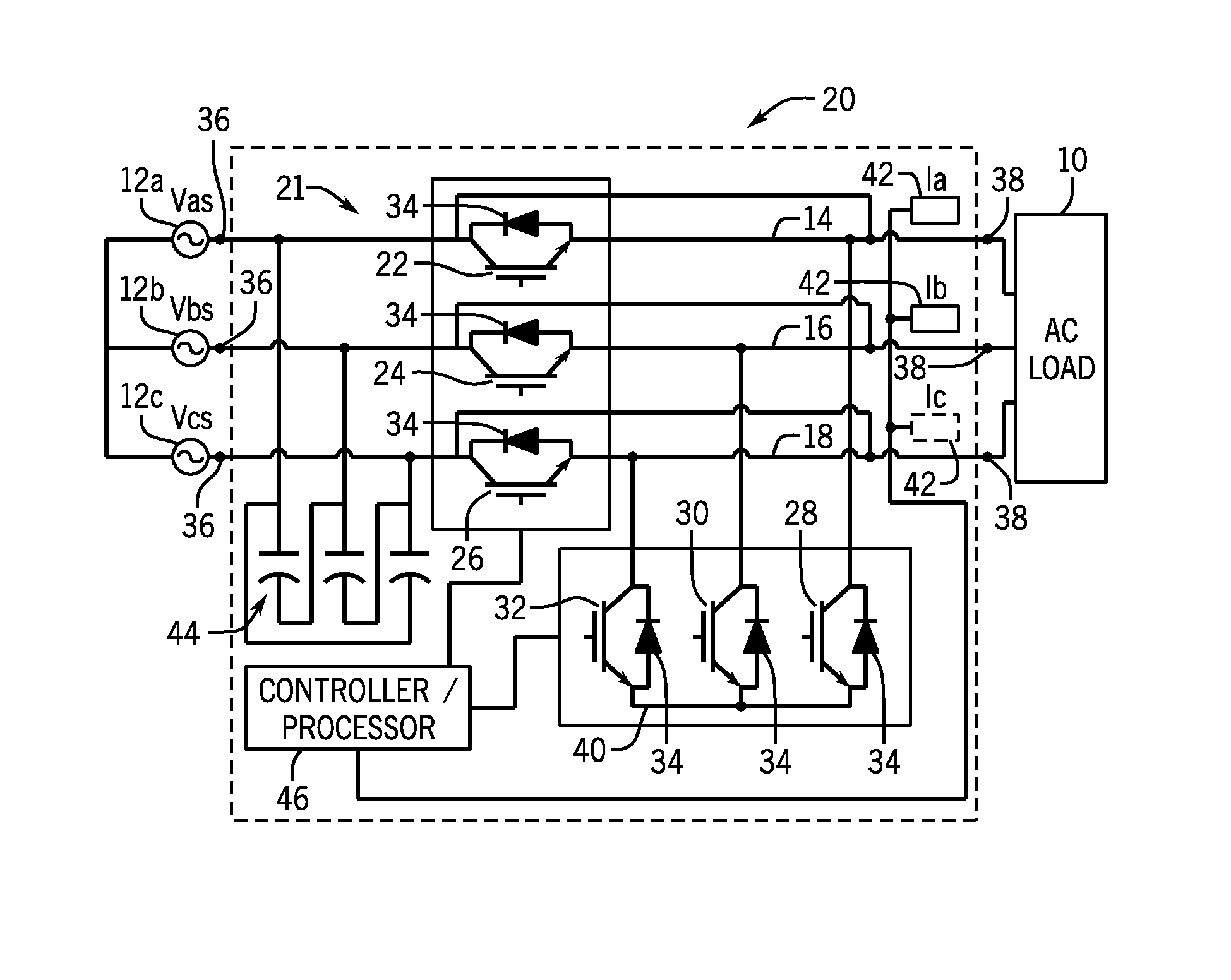
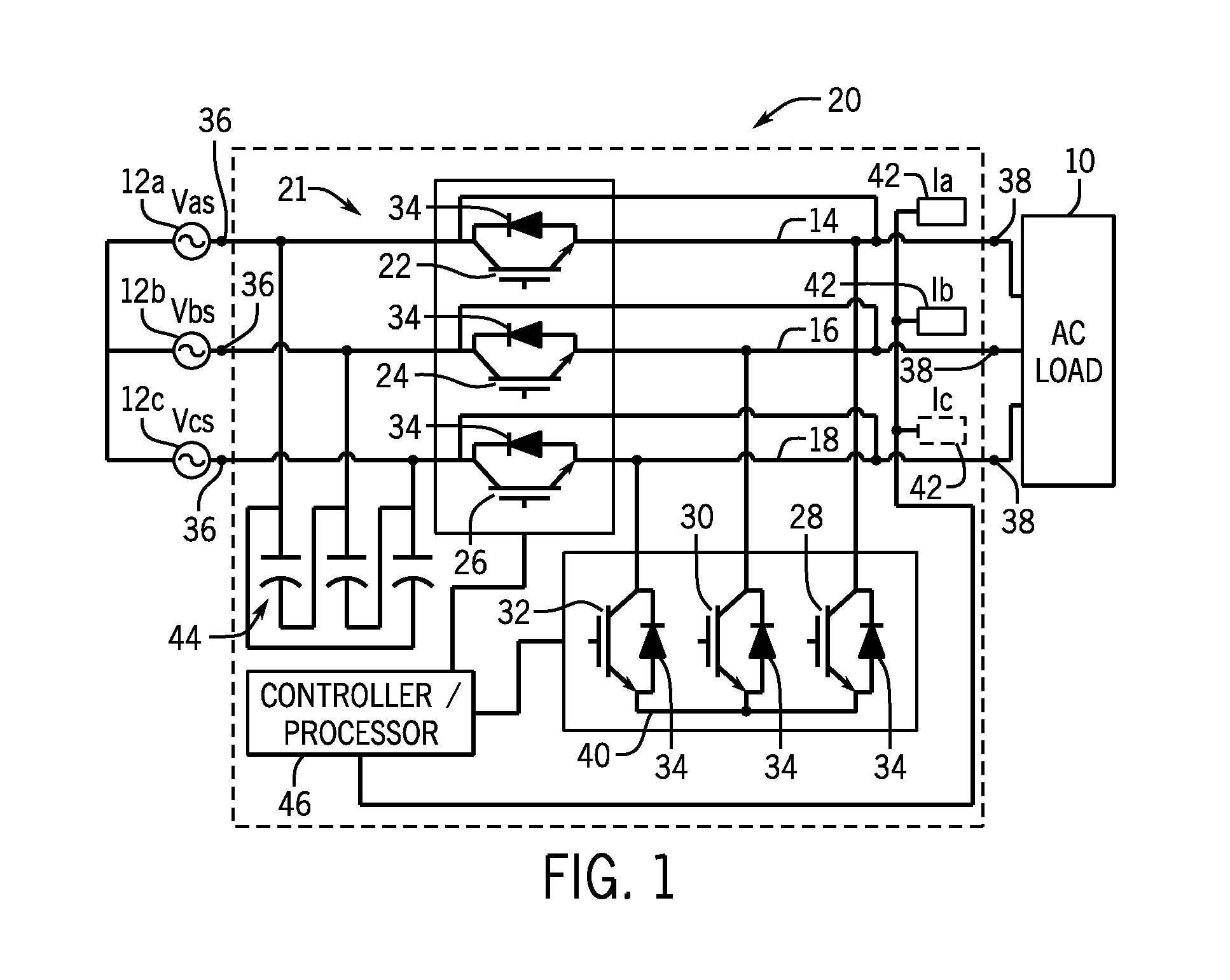
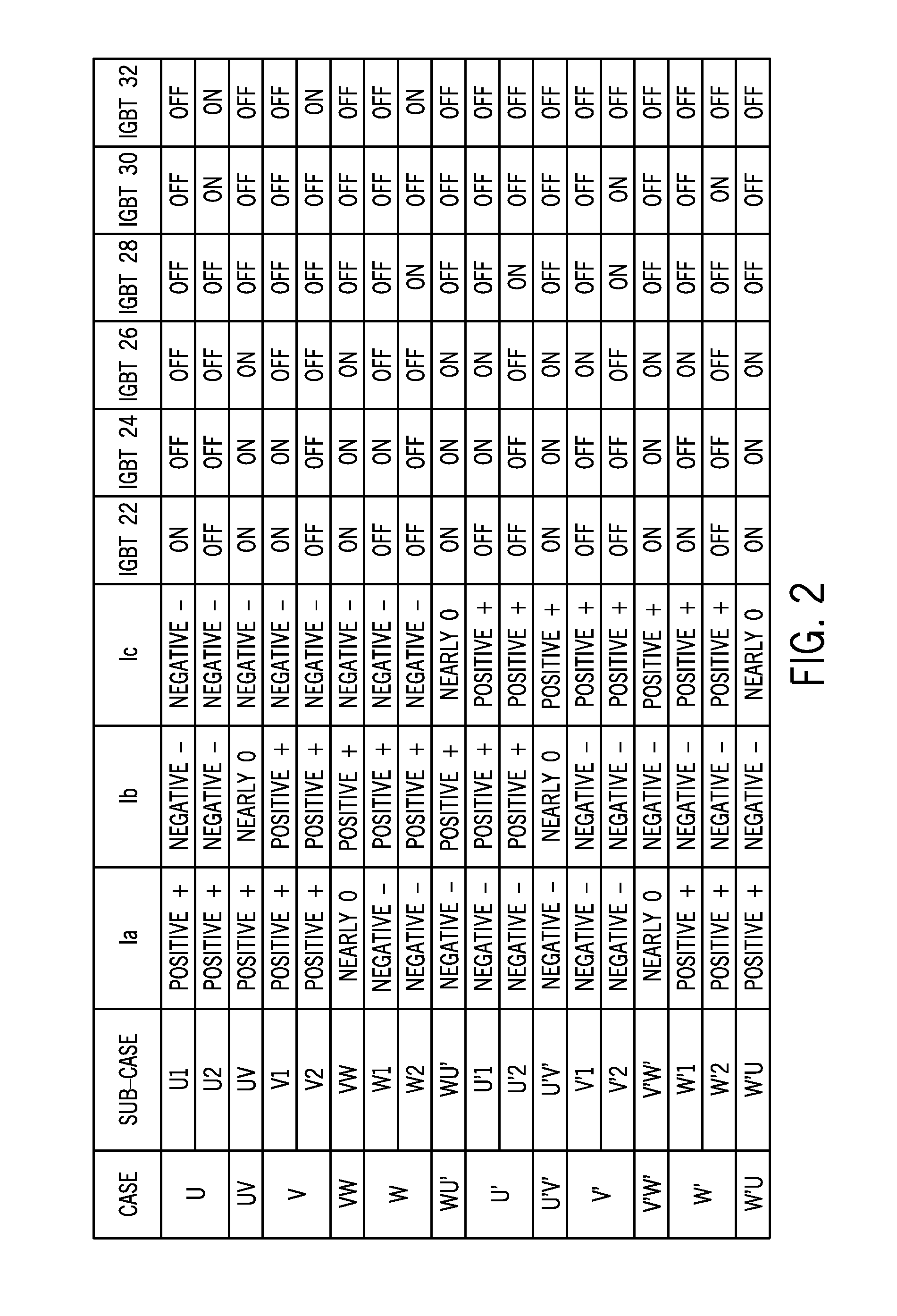
[0029]In a first example, as a result of the initial routine, it is determined that Current Ia is positive while both Ib and Ic are negative (State U). Then, IGBT 22 (i.e., the line-side IGBT in Phase A) is left ON and all other IGBTs 24, 26, 28, 30, 32 are turned OFF or left OFF. Full line voltage is then applied to the load terminals 38 during an active period. This is Sub-State U1 in FIG. 2. At any time (i.e., “control time”) during this State U, the voltage at the load terminals 38 can be switched from line voltage to zero by turning OFF IGBT 22 and turning ON IGBTs 30, 32 (Sub-State U2), so as to transition to a free-wheeling period. IGBTs 30, 32 are the two floating-neutral side IGBTs that are not in Phase A. The “control time”, therefore, divides State U into two periods, first an active period, second a free-wheeling period. The ratio of the active period over the sum of the active period and the free-wheeling period is referred to as the duty cycle, and is a key element in ...

example 2

[0032]In a second example, two of the currents are positive, such as Ia and Ib, while the third one (Ic) is negative. This is State V in FIG. 2. In such a case, the line-side IGBTs 22, 24 in those two phases will be in the ON condition during an “active period” while all other IGBTs 26, 28, 30, 32 are OFF (see Sub-State V1). A “free-wheeling period” can be similarly obtained by turning OFF these two switches IGBTs 22, 24, and turning ON IGBT 32 in the third phase (Sub-State V2).

[0033]The same logic applies in the states labeled W, or U′, V′, and W′ in FIG. 2. In particular, States U′, V′, and W′ are mirror images of States U, V, W, with whichever current is positive in State U, V, or W, being negative in States U′, V′, and W′, and vice-versa.

[0034]With respect to the switching logic described in FIG. 2, it is recognized that the switching logic is predicated on the accurate sensing of the direction / sign of the current in all phases. However, due to current signal noise or other poss...


PUM


Abstract

A system and method for controlling switching in an AC-AC converter is disclosed. A controller for the AC-AC converter determines a direction of current flow on supply lines that provide AC power to the AC-AC converter and determines a switching pattern for each of a plurality of line-side switches and each of a plurality of floating-neutral side switches in the AC-AC converter based on the determined direction of current flow on each of the supply lines. The controller causes the line-side switches and the floating-neutral side switches to operate in an ON or OFF condition according to the determined switching pattern, such that a controlled current flow is output from the AC-AC converter. The controller also implements a safe-switching routine when transitioning from a first switching pattern to a second switching pattern that prevents a non-zero current from being interrupted during the transitioning between the first and second switching patterns.

Description

BACKGROUND OF THE INVENTION[0001]The present invention relates generally to AC-to-AC electronic converters and, more particularly, to an AC-to-AC converter and method of operation thereof that provides for safe switching in the AC-to-AC converter that avoids voltage spikes during switching transitions.[0002]AC-AC converters function to convert an AC voltage to another AC voltage. One type of AC-AC converters commonly used in industry are soft starters, which are industrial control devices that make it possible to start AC induction motors smoothly, with a reduced inrush current. Soft starters typically employ silicon controlled rectifiers (SCRs) for reducing voltage applied to the motor and thus reducing the starting inrush current to the motor. While SCRs can be turned on at will, they cannot be turned off in a dynamic and controllable fashion, as SCRs turn off naturally when the current reaches zero. SCRs thus lack the desired capability to provide precise control over current—wit...

Claims


Application Information

Patent Timeline
Patent Type & Authority Applications(United States)
IPC IPC(8): H02M5/293H02M1/00
CPCH02M2005/2932H02M5/293Y02B70/10H02M1/0058H02M5/2932
Inventor LEQUESNE, BRUNO PATRICE-BERNARDFAMILIANT, YAKOV LVOVICHFU, QIANGBHAVARAJU, VIJAY
Owner EATON INTELLIGENT POWER LIMITED
Why Eureka
Try Eureka