Power router and operation control method thereof, power network system, and non-transitory computer readable media storing program

a technology of operation control and router, which is applied in the direction of power network operation system integration, ac network voltage adjustment, efficient power electronics conversion, etc., to achieve the effect of managing or controlling the power router more appropriately

Inactive Publication Date: 2015-12-10
NEC CORP
View PDF4 Cites 5 Cited by
  • Summary
  • Abstract
  • Description
  • Claims
  • Application Information

AI Technical Summary

Benefits of technology

[0019]According to the present invention, it is possible to manage or control a power router more appropriately when a power network system in which power cells are asynchronously connected with each other.

Problems solved by technology

When a power supply system is constructed, in addition to a further expansion of a power distribution grid in a more stable way, a main issue has been providing such a system with a capability of introducing a large amount of natural energy.

Method used


Image

  • Power router and operation control method thereof, power network system, and non-transitory computer readable media storing program
  • Power router and operation control method thereof, power network system, and non-transitory computer readable media storing program
  • Power router and operation control method thereof, power network system, and non-transitory computer readable media storing program

Examples


first exemplary embodiment

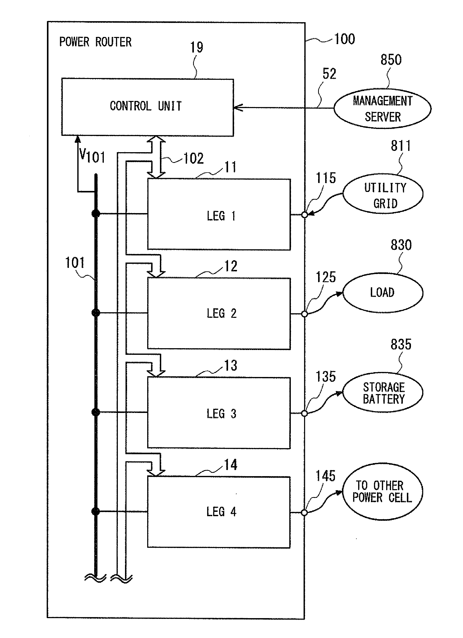
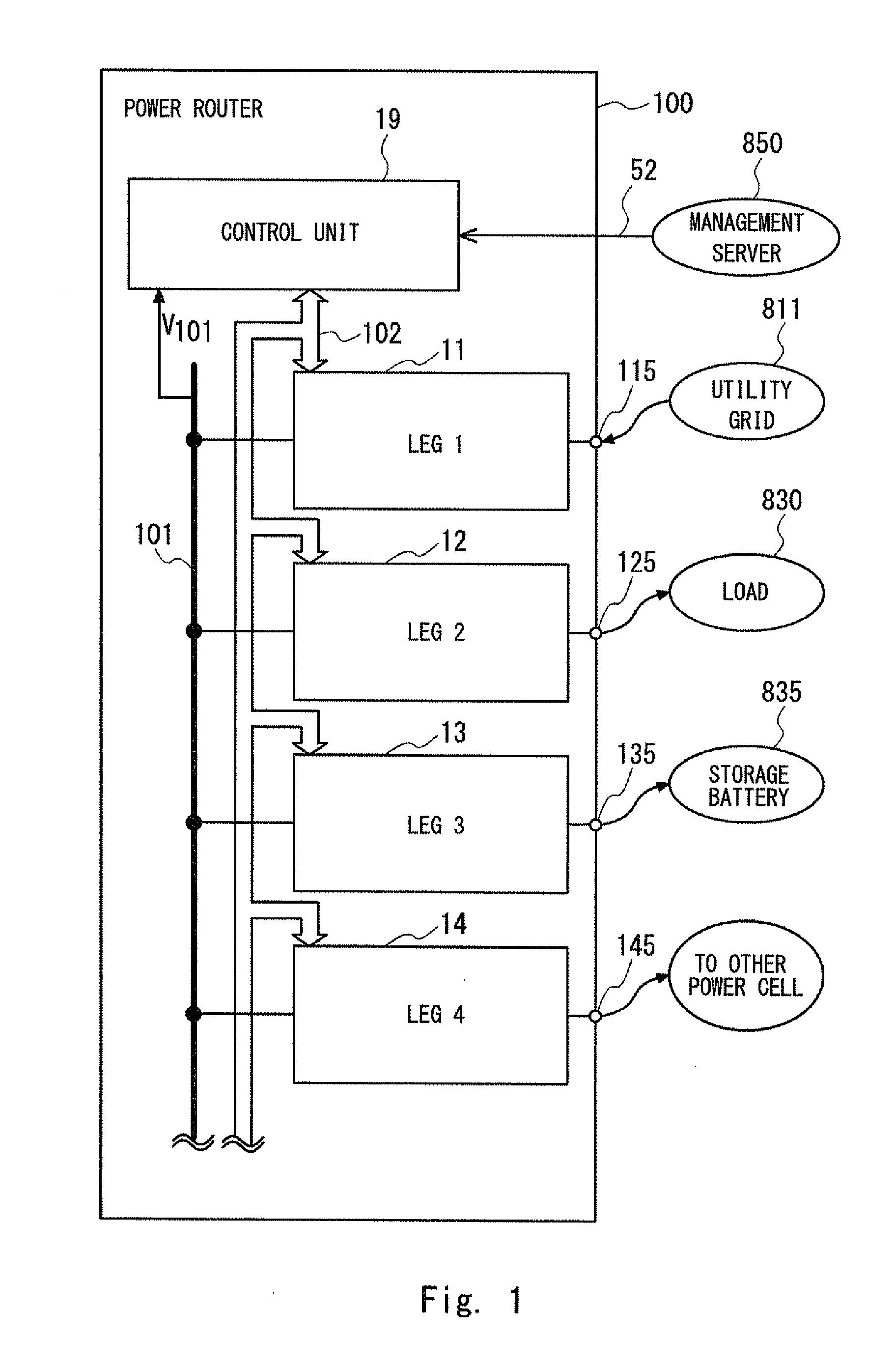
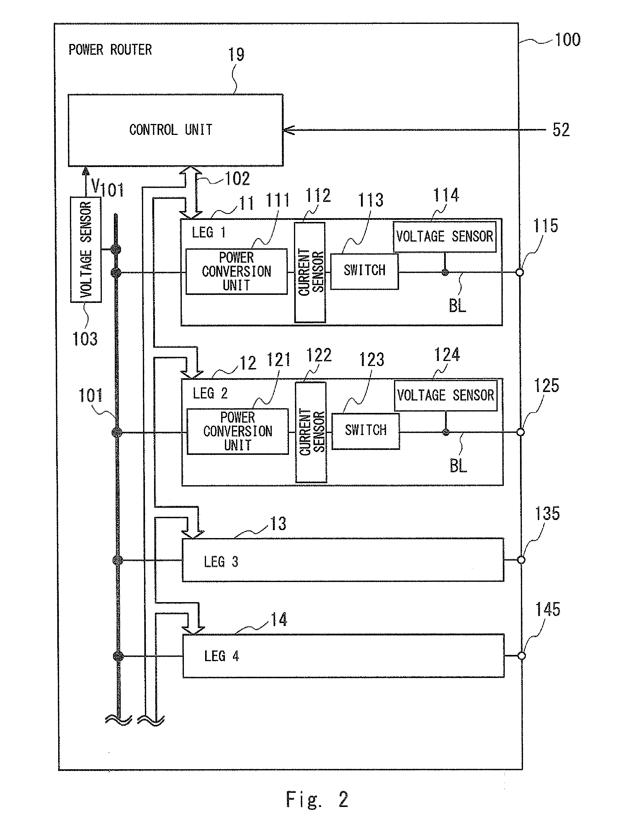
[0036]Stopping of a leg included in a power router will be described in the present exemplary embodiment. Here, a power router 100 according to a first exemplary embodiment will be firstly described. The power router 100 is a specific example of above power routers 841 to 844 (FIG. 15). FIG. 1 is a block diagram illustrating a schematic configuration of the power router 100. The power router 100 typically includes a direct current (DC) bus 101, a first leg 11, a second leg 12, a third leg 13, a fourth leg 14 and a control unit 19. In addition, in FIG. 1, the first leg to the fourth leg are indicated as a leg 1 to a leg 4, respectively, for convenience of the drawings.

[0037]The DC bus 101 is connected with the first leg 11 to the fourth leg 14 in parallel. The DC bus 101 is provided to enable DC power flow. The control unit 19 maintains a bus voltage V101 of the DC bus 101 at a predetermined fixed value by controlling operation states of the first leg 11 to the fourth leg 14 (an oper...

second exemplary embodiment

[0122]Next, a power router 200 according to a second exemplary embodiment will be described. The power router 200 is a modification of the power router 100 according to the first exemplary embodiment. The power router 200 can further change the operation mode after the stopping target leg described in the first exemplary embodiment is stopped. That is, in the power router 200, a process to activate the stopped leg in the operation mode designated by the management server 850 is performed after the stopping target leg is stopped. Since a configuration and the stopping operation of the stopping target leg the power router 200 are similar to those of the power router 100, descriptions of those will be omitted.

[0123]Subsequently, a specific procedure of activation after the leg is stopped when the operation mode is changed will be described. In the present exemplary embodiment, the management server 850 designates the operation mode in a manner that the stopping target leg is an activat...

third exemplary embodiment

[0151]Next, a third exemplary embodiment will be described. In the present exemplary embodiment, an example of a power network system configured by using one or more power routers will be described. Note that the power network system is configured by using power routers 1011 to 1014, and any power routers according to the first and second exemplary embodiments may be used as each of the power routers 1011 to 1014.

[0152]FIG. 12 is a block diagram schematically showing a configuration of a power network system 1001 that is an example of a power network system. In FIG. 12, for simplifying the drawing, numerical signs of the legs are omitted. White circle attached to the power routers 1011 to 1014 represent connection terminals, respectively.

[0153]Here, a connection line connecting the power router with connection partner will be complemented. When a connection line connecting the power routers with each other is referred to as a power transmission line, the power transmission line may ...


PUM


Abstract

A management or control of a power router is more appropriately performed when a power network system in which power cells are asynchronously connected with each other. A plurality of power conversion legs bi-directionally convert power, one ends thereof are connected with a direct current bus and the other ends thereof are connected with an external connection partner as an external connection terminal. A control unit controls operations of the plurality of power conversion legs. The control unit receives a control instruction including a designation of a stopping target leg. The control unit performs an adequacy determination of whether the stopping target leg can be stopped. The control unit stops the stopping target leg when the stopping target leg can be stopped.

Description

TECHNICAL FIELD[0001]The present invention relates to a power router and an operation control method thereof, a power network system, and a non-transitory computer readable media storing program.BACKGROUND ART[0002]When a power supply system is constructed, in addition to a further expansion of a power distribution grid in a more stable way, a main issue has been providing such a system with a capability of introducing a large amount of natural energy. A power network system called Digital Grid (registered trademark) has been proposed as a new power network (see Patent literatures 1 and 2.[0003]Digital Grid (registered trademark) is a power network system in which a power network is partitioned into small-sized cells and these cells are asynchronously interconnected. Each power cell may be small (e.g., a house, a building, or a commercial facility) or may be large (e.g., a prefecture or a municipality). Each power cell naturally includes a load, and may also include a power generati...

Claims


Application Information

Patent Timeline
Patent Type & Authority Applications(United States)
IPC IPC(8): H02M1/36H02J5/00H02M7/70
CPCH02M1/36H02J5/00H02M7/70H02M7/493H02J3/06Y02B70/3225Y04S20/222H02J2310/12H02J13/00017H02J13/00004H02J13/00028H02J3/14Y02B70/10Y04S40/124Y02E60/00H02M1/0032H02M1/0054H02J7/02
Inventor KOBAYASHI, NORIAKI
Owner NEC CORP
Why Eureka
Try Eureka