Pry bar

Inactive Publication Date: 2016-01-28
KASAN ELI
View PDF2 Cites 24 Cited by
  • Summary
  • Abstract
  • Description
  • Claims
  • Application Information

AI Technical Summary

Problems solved by technology

Commercially available pry bars slip off a lower support structure (such as joints) when prying attachment devices (such as nails or screws) from architectural members (such as deck boards) because the two paws or distal ends of the hook members are not fully engaged with a lower support structure throughout the prying operation.

Method used


Image

  • Pry bar
  • Pry bar
  • Pry bar

Examples


Embodiment Construction

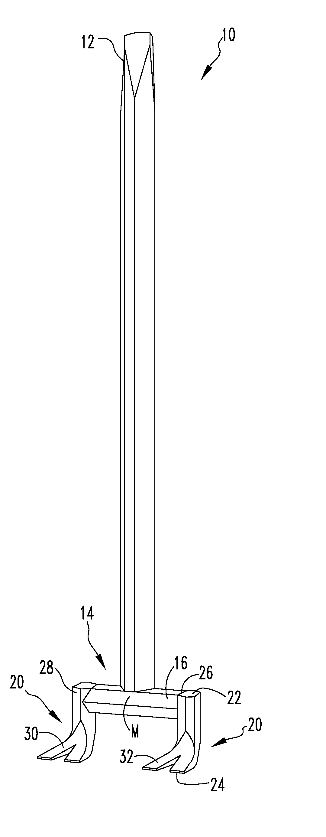
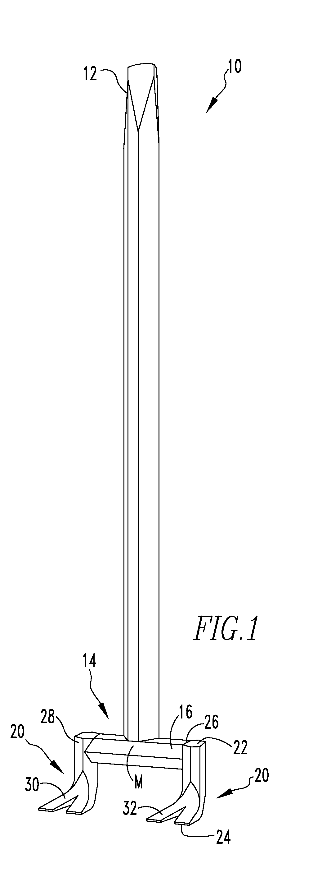
[0011]Referring now to FIGS. 1-5, in which like numerals indicate like parts, the pry bar of the present invention is shown generally at 10 for facilitating prying a flat member, such as a deck board (not shown), from slender members, such as joists (not shown).

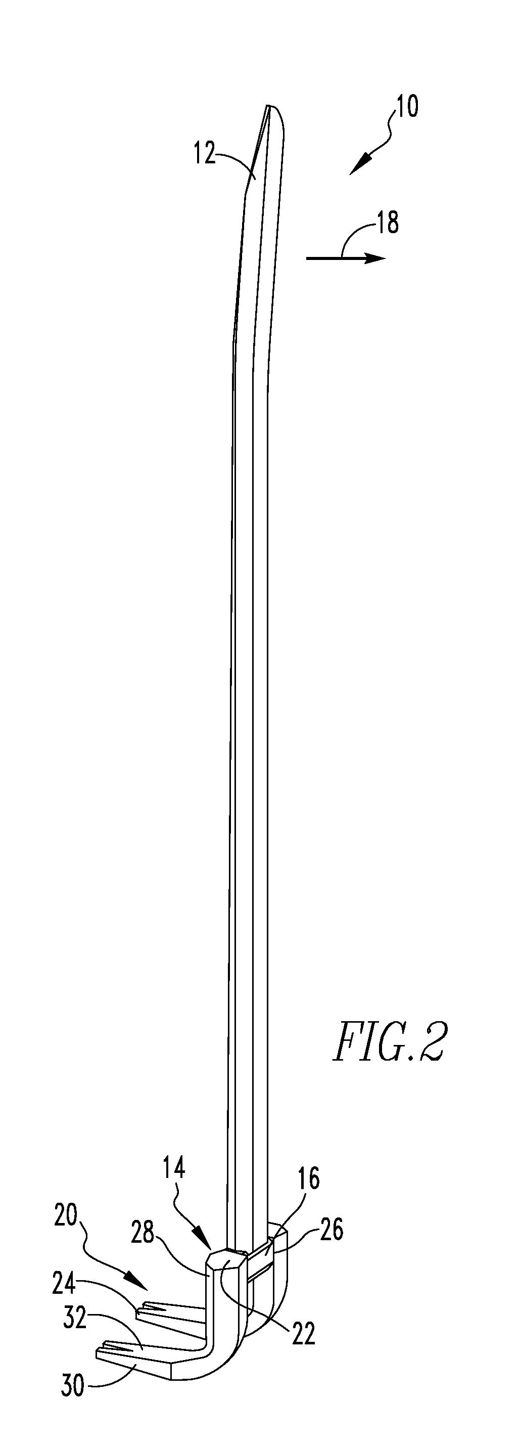
[0012]The pry bar 10 comprises a handle 12 and a head 14. The head 14 extends perpendicularly from the handle 12 at the midpoint M of the head 14. The head 14 is used for engaging under the flat member and functions as a fulcrum 16 by engaging the slender members and thereby causing the head 14 to pry the flat member from the slender members when the handle 12 is pushed away from the head 14 in a direction of arrow 18 (FIG. 2) by the fulcrum 16 pivoting on the slender member.

[0013]The head 14 comprises a fulcrum 16 and a pair of L-shaped paw members 20. The pair of L-shaped members 20 each have proximal ends 22, respectively, and distal ends 24, respectively.

[0014]The handle 12 is elongated and generally straight, for example...


PUM


Abstract

Pry bars that will not slip off a lower support structure (such as joints) when prying attachment devices (such as nails or screws) from architectural members (such as deck boards) because the two paws or distal ends of the hook members are fully engaged with one or more lower support structures throughout the prying operation. The pry bar has a handle and a head, with the head having a fulcrum and two hook or paw members.

Description

CROSS-REFERENCE TO RELATED APPLICATIONS[0001]This nonprovisional patent application claims priority to U.S. Provisional Application Ser. No. 62 / 027,530, titled PRY BAR, filed Jul. 22, 2014, which is incorporated by reference herein in its entirety.FIELD OF THE INVENTION[0002]The invention relates generally to a pry bar.BACKGROUND AND SUMMARY OF THE INVENTION[0003]Commercially available pry bars slip off a lower support structure (such as joints) when prying attachment devices (such as nails or screws) from architectural members (such as deck boards) because the two paws or distal ends of the hook members are not fully engaged with a lower support structure throughout the prying operation.[0004]The present invention addresses the issue through use of a modified pry bar that includes a pair of L-shaped paw members that can be angled to address the slippage issue.BRIEF DESCRIPTION OF THE DRAWINGS[0005]Embodiments of the present invention will now be described, by way of example only, w...

Claims


Application Information

Patent Timeline
Patent Type & Authority Applications(United States)
IPC IPC(8): B66F15/00
CPCB66F15/00E04G23/08E04G2023/085
Inventor KASAN, ELI
Owner KASAN ELI
Why Eureka
Try Eureka