Humidification device

a technology of humidification device and humidifier, which is applied in the direction of domestic cooling apparatus, lighting and heating apparatus, heating types, etc., can solve the problems of deterioration of the comfort of passengers provided by air conditioning cooling head and heating feet, complicated configuration of humidification device, and increase of manufacturing cost, so as to prevent the temperature of humidified air from increasing unnecessarily, complicated configuration of humidification device, and the effect of increasing the manufacturing cos

Active Publication Date: 2016-02-25
DENSO CORP
View PDF9 Cites 8 Cited by
  • Summary
  • Abstract
  • Description
  • Claims
  • Application Information

AI Technical Summary

Benefits of technology

[0008]Patent Document 1 proposes an idea of blowing air to the passenger after cooling the air having high-temperature and high-humidity by using a cooler such as a peltier element to humidify the vehicle compartment. However, disposing a cooler such as a peltier element in addition to a heating device heating the adsorption agent may make a configuration of the humidification device complicated and may cause an increase of a manufacturing cost.
[0009]The present disclosure addresses the above issues, and it is an objective of the present disclosure to provide a humidification device that can prevent a temperature of humidified air from increasing unnecessarily.
[0016]That is, since air in the humidification-subject space can be humidified without heating the adsorption agent, a device for heating the adsorption agent is not necessary. Furthermore, a temperature of humidified air does not increase. Therefore, according to the humidification device of the present disclosure, a temperature of humidified air can be prevented from increasing unnecessarily with a simple configuration.

Problems solved by technology

When air having high-temperature and high-humidity is blown toward a face and an upper body of the passenger, a convenient felling of the passenger provided by an air conditioning cooling the head and heating the feet is deteriorated.
However, disposing a cooler such as a peltier element in addition to a heating device heating the adsorption agent may make a configuration of the humidification device complicated and may cause an increase of a manufacturing cost.

Method used


Image

  • Humidification device
  • Humidification device
  • Humidification device

Examples


Embodiment Construction

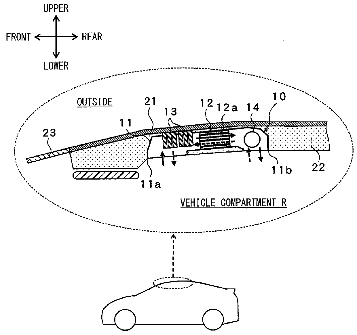
[0023]An embodiment of the present disclosure will be described hereafter referring to drawings. In the present embodiment, a humidification device 10 of the present disclosure is used for a vehicle. Accordingly, a humidification-subject space is a vehicle compartment R in the present embodiment. Further, the vehicle has a vehicle air conditioner adjusting a temperature in the vehicle compartment R in addition to the humidification device 10.

[0024]As shown in FIG. 1, the humidification device 10 is located on a roof side in the vehicle. In FIG. 1, each arrow indicating upper, lower, right, or left respectively indicates upper, lower right, or left on a condition where the humidification device 10 is disposed in the vehicle. The humidification device 10 has a casing 11 providing an outer wall of the humidification device 10, and the casing 11 houses an adsorption agent module 12, a heat sink 13, a blower 14, and the like.

[0025]The casing 11 is made of resin or metal to have a box sha...


PUM


Abstract

In an adsorption operation in which the adsorption agent adsorbs water, air in a vehicle compartment flows into an adsorption agent module after being cooled by passing around a heat sink. On the other hand, in a desorption operation in which the water is desorbed from the adsorption agent, the air in the vehicle compartment flows into the adsorption agent module to be humidified without being heated or cooled, and humidified air is cooled by passing around the heat sink and blown into the vehicle compartment. Accordingly, a temperature of the humidified air can be prevented from increasing unnecessarily by a simple configuration with which the air in the vehicle compartment is cooled in the heat sink.

Description

CROSS REFERENCE TO RELATED APPLICATION[0001]This application is based on Japanese Patent Application No. 2013-79427 filed on Apr. 5, 2013, the disclosure of which is incorporated herein by reference.TECHNICAL FIELD[0002]The present disclosure relates to a humidification device for humidifying air by water desorbed from an adsorption agent.BACKGROUND ART[0003]Conventionally, a so-called desiccant system is known to alternately switch between an adsorption operation in which water is adsorbed on an adsorption agent and a desorption operation in which the water is desorbed from the adsorption agent by heating the adsorption agent that is after adsorbing water. Accordingly, the adsorption agent is recovered. Patent Document 1 discloses a humidification device using the desiccant system.[0004]More specifically, the humidification device of Patent Document 1 is for a vehicle and performs a desorption operation of the adsorption agent by heating the adsorption agent using an electric heate...

Claims


Application Information

Patent Timeline
Patent Type & Authority Applications(United States)
IPC IPC(8): F24F3/14B60H3/02F24F6/08
CPCF24F3/1429B60H3/02F24F6/08B60H3/022B60H2003/028F24F3/1411
Inventor KOMATSUBARA, YUSUKE
Owner DENSO CORP
Why Eureka
Try Eureka