Damper with air spring

a technology of air springs and dampers, which is applied in the direction of shock absorbers, mechanical devices, transportation and packaging, etc., can solve the problems of complicated configuration and complicated damper configuration, and achieve the effects of convenient attachment and removal, and smooth insertion

Active Publication Date: 2015-12-08
HITACHI ASTEMO LTD
View PDF39 Cites 8 Cited by
  • Summary
  • Abstract
  • Description
  • Claims
  • Application Information

AI Technical Summary

Benefits of technology

[0008]If the first end of the diaphragm is attached to a side of the cylinder of the damper main body by the welding method, a sliding range of the cylinder within which the piston slides needs to be prevented from undergoing welding distortion. Thus, a welded portion is limited to a lower end of the cylinder, which falls out of the sliding range, or the cylinder needs to be a double cylinder including an internal cylinder and an outer cylinder so that the welded portion is provided on the external cylinder over which the piston does not directly slide. As a result, the configuration of the damper is complicated.

Problems solved by technology

As a result, the configuration of the damper is complicated.

Method used


Image

  • Damper with air spring
  • Damper with air spring
  • Damper with air spring

Examples


Embodiment Construction

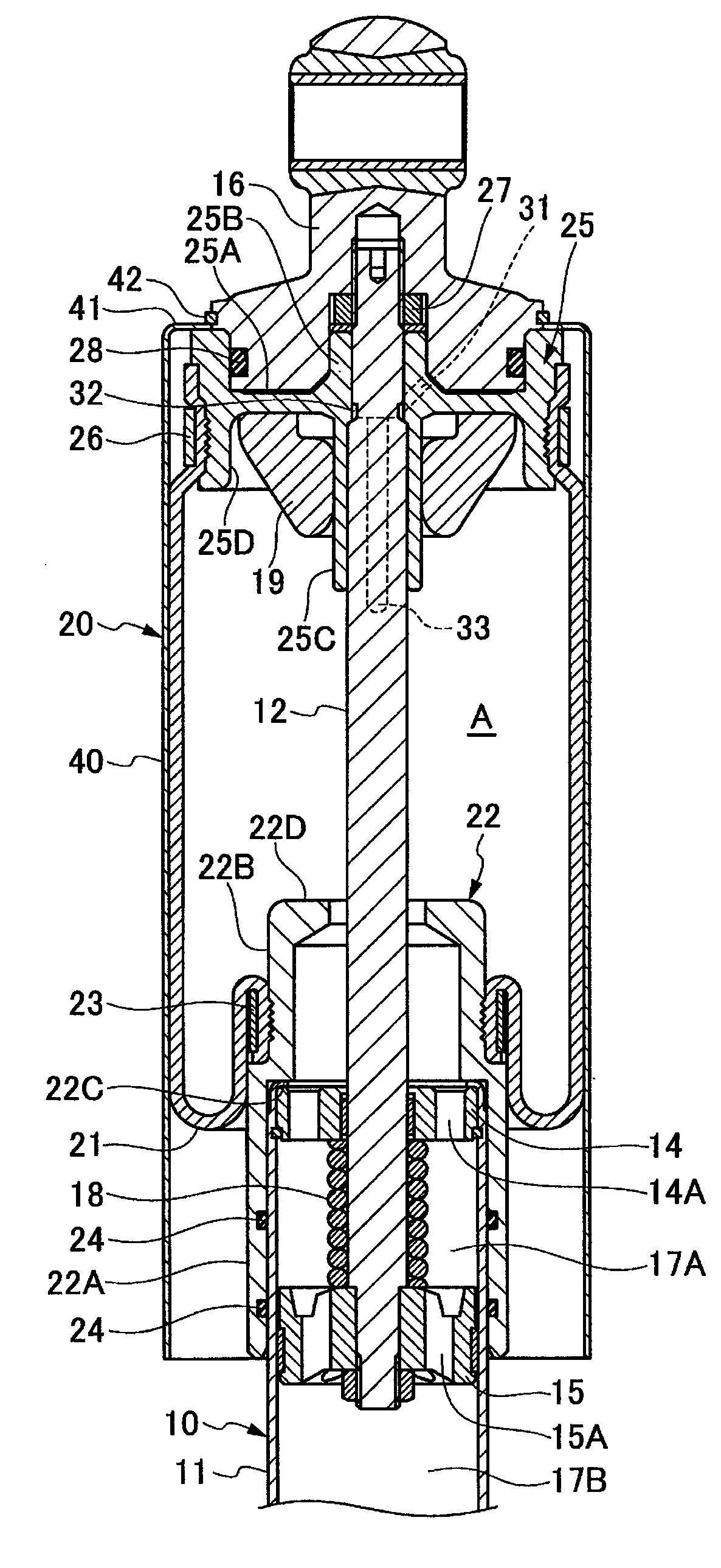
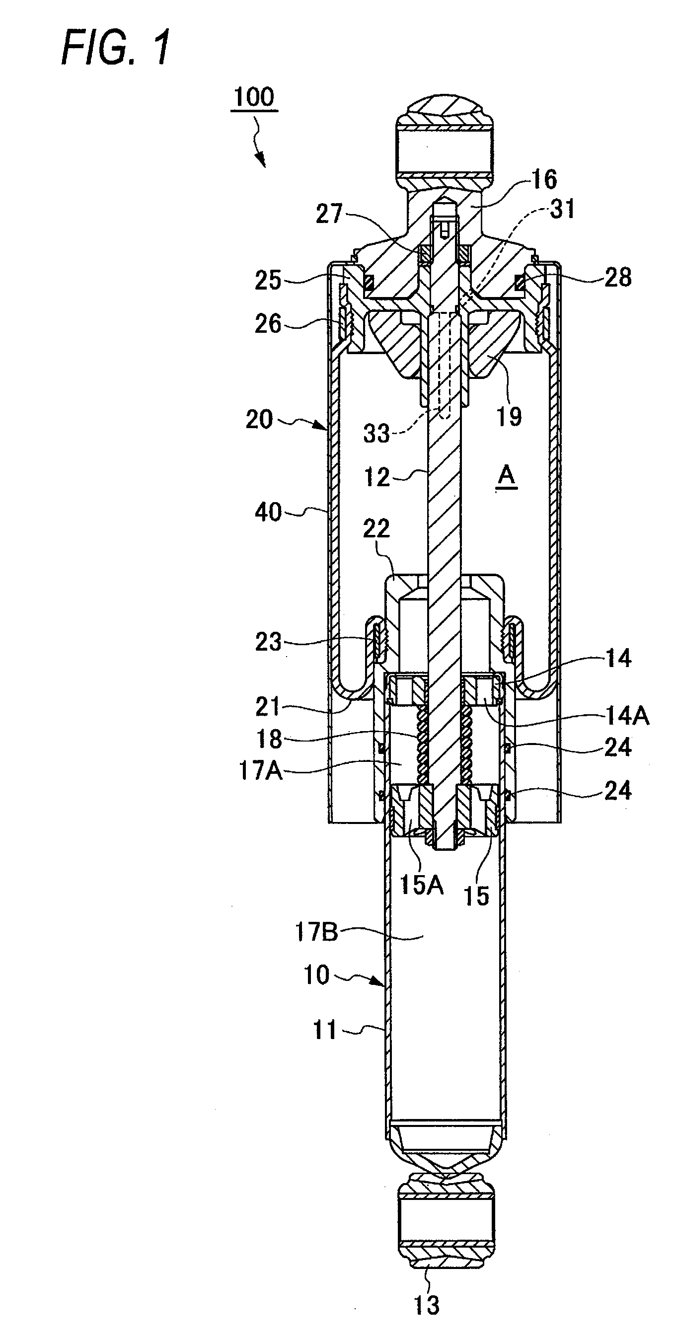
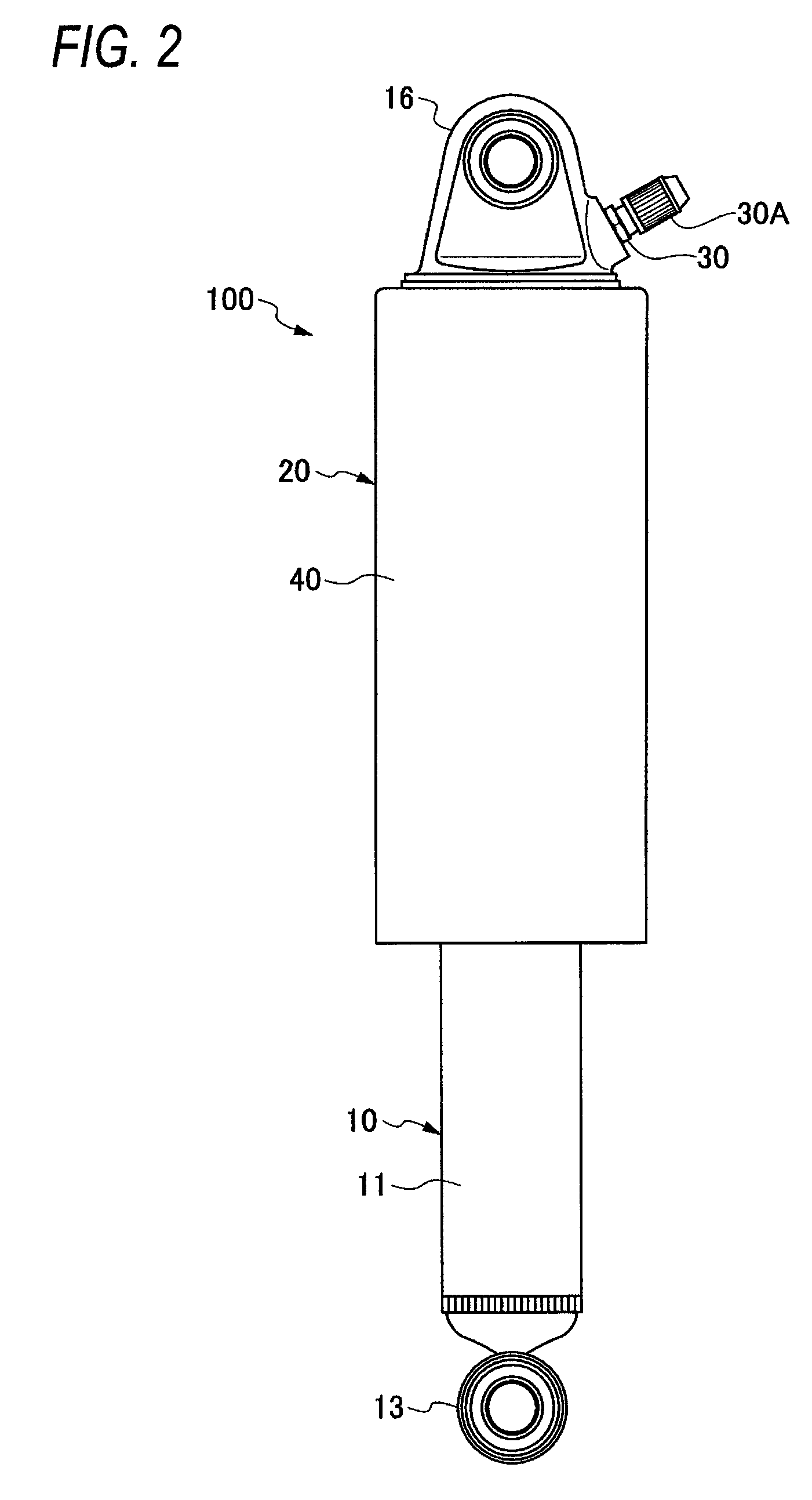
[0030]As shown in FIG. 1 to FIG. 3, a damper with an air spring 100 is an assembly of a damper main body 10 and a diaphragm structure 20. The damper main body 10 includes a cylinder 11 and a piston rod 12 that is inserted into the cylinder 11. A diaphragm 21 forming the diaphragm structure 20 is formed of cylindrical rubber and is attached to a side of the cylinder 11 at a first end thereof and to a side of the piston rod 12 at a second end thereof to form an air chamber A around the damper main body 10.

[0031]As shown in FIG. 1 and FIG. 4, the damper main body 10 includes an axle side attachment member 13 attached to a bottom portion of the cylinder 11 and a rod guide 14 fixedly provided in an opening in the cylinder 11. Furthermore, the damper main body 10 includes a piston 15 fixedly provided at an insertion end of the piston rod 12 that is inserted into the cylinder 11 through the rod guide 14. A vehicle body side attachment member 16 is attached to a leading-end reduced diameter...


PUM


Abstract

A damper with an air spring includes: a damper main body having a cylinder and a piston rod inserted into the cylinder; and a cylindrical diaphragm attached to a side of the cylinder at a first end thereof and to a side of the piston rod at a second end thereof and forming an air chamber around the damper main body, in which a first attachment case to which the first end of the diaphragm is attached is fitted on an outer periphery of the cylinder, and an inner-diameter step portion of the first attachment case is brought into abutting contact with an upper end portion of the cylinder in an axial direction thereof, while a second attachment case to which the second end of the diaphragm is attached is fixed to the piston rod.

Description

CROSS-REFERENCE TO RELATED APPLICATIONS[0001]This application is based on and claims priority under 35 U.S.C. 119 from Japanese Patent Application No. 2012-281736 filed on Dec. 25, 2012, the entire content of which is incorporated herein by reference.BACKGROUND[0002]1. Technical Field[0003]The present invention relates to a damper with an air spring.[0004]2. Related Art[0005]A damper with an air spring is available which includes a damper main body with a cylinder and a piston rod inserted into the cylinder and a cylindrical diaphragm which is attached to a side of the cylinder at a first end thereof and to a side of the piston rod at a second end thereof to form an air chamber around the damper main body. A method for attaching the first end of the diaphragm to the cylinder of the damper main body is based on welding or crimping.[0006]The method based on welding involves welding a piston pipe to which the first end of the diaphragm is attached, to an outer periphery of the cylinder...

Claims


Application Information

Patent Timeline
Patent Type & Authority Patents(United States)
IPC IPC(8): F16F9/02B60G15/12F16F9/088B60G15/14F16F9/04
CPCF16F9/088B60G15/12B60G15/14F16F9/0472B60G2202/152B60G2202/24B60G2204/45B60G2202/314
Inventor SUGATA, NORIHISA
Owner HITACHI ASTEMO LTD
Why Eureka
Try Eureka