Optical head, optical information apparatus, and optical-information reproducing method

Active Publication Date: 2005-12-15
PANASONIC CORP
View PDF3 Cites 8 Cited by
  • Summary
  • Abstract
  • Description
  • Claims
  • Application Information

AI Technical Summary

Benefits of technology

[0007] In order to resolve the above described conventional disadvantage, it is an object of the present invention to provide an optical head, an optical information apparatus and an optical-information reproducing method

Problems solved by technology

This presents a disadvantage in that a tracking signal has an offset when a

Method used


Image

  • Optical head, optical information apparatus, and optical-information reproducing method
  • Optical head, optical information apparatus, and optical-information reproducing method
  • Optical head, optical information apparatus, and optical-information reproducing method

Examples


first embodiment

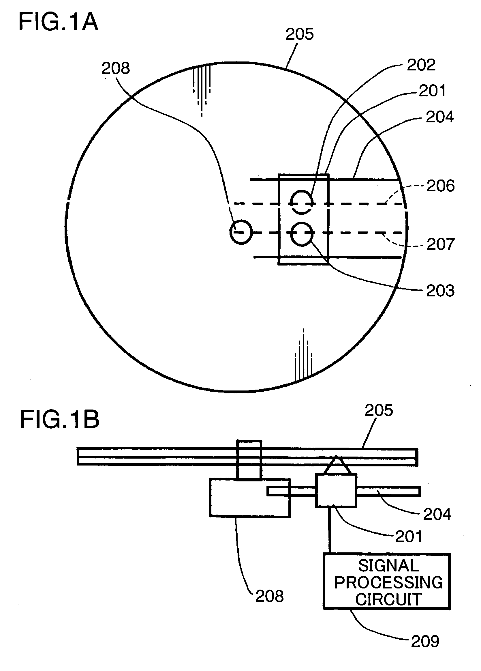
[0030]FIGS. 1A and 1B schematically show the configuration of an optical information apparatus according to a first embodiment of the present invention. In FIGS. 1A and 1B, description is omitted about the same component elements as those of FIGS. 14 and 15.

[0031] In FIG. 1A, an optical head 201 includes a first objective lens (i.e., the light-concentrating means or the light-concentrating element) 202, and a second objective lens (i.e., the light-concentrating means or the light-concentrating element) 203. The optical head 201 is transferred from the inner circumference to the outer circumference of an optical disk (i.e., the information storage medium) 205 by a transfer mechanism (i.e., the transferring means) 204. At this time, the first objective lens 202 moves on a straight line 206, and the second objective lens 203 moves on a straight line 207 parallel to the straight line 206. In other words, the straight line 206 is a transfer line of the first objective lens 202, and the ...

second embodiment

[0059]FIG. 8 schematically shows an optical head according to a second embodiment of the present invention. In this second embodiment, an optical beam which returns from the optical disk 205 is split by a hologram element 400 as an example of the splitting means. In FIG. 8, the same component elements as those of FIG. 1 and FIG. 3 are given the identical reference numerals, and thus, their description is omitted.

[0060] In FIG. 8, the hologram element 400 splits the optical beam which has been reflected by the optical disk 205 and has passed through by the collimator lens 222 and the beam splitter 221. Then, it diffracts an optical beam which is a part of it and changes the direction in which it goes ahead. The optical beam which has been diffracted by the hologram element 400 and the optical beam which has gone straight without being diffracted are given astigmatism by the cylindrical lens 224. Then, it is received by a photo-detector (i.e., the detecting means) 401.

[0061]FIG. 9A ...

third embodiment

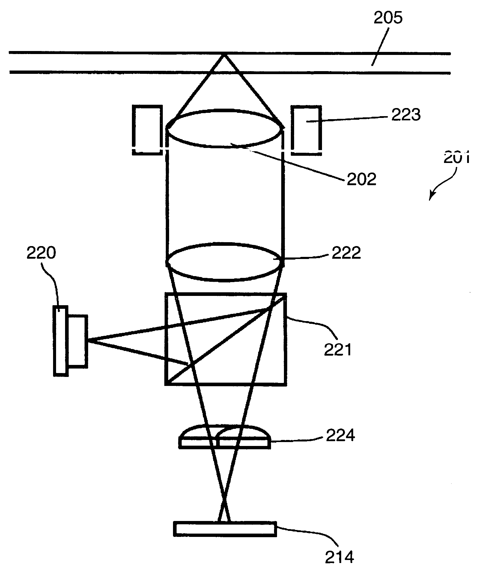
[0076]FIG. 12 schematically shows the main part of an optical information apparatus which is provided with an optical head 610 according to a third embodiment of the present invention. In this FIG. 12, the same component elements as those of FIG. 1 and FIG. 3 are given the identical reference numerals, and thus, their description is omitted.

[0077] A beam of light which is emitted from the semiconductor laser (i.e., the light source) 220 is reflected by the beam splitter 221. Then, it passes through the collimator lens 222 and is reflected by a raising prism 601. Next, it is concentrated by the first objective lens 202 and irradiates the optical disk 205. The beam of light which is reflected and diffracted by the optical disk 205 follows the same path again and passes through the beam splitter 221. Then, a part of it is diffracted by the hologram element 400 and penetrates the cylindrical lens 224. Thereafter, it is received by the photo-detector 401.

[0078] On the other hand, a par...


PUM


Abstract

An optical head is provided which is capable of realizing a stable tracking control, even if the rotational center of an information recording medium is not located on the extension line of the transfer directions of a light-concentrating element. This optical head includes: a semiconductor laser which emits a beam of light; an objective lens which concentrates the beam of light on an optical disk; a transfer mechanism which transfers the objective lens between the outermost circumference and the innermost circumference of the recording area of the optical disk along the optical disk; and a photo-detector which detects a beam of light that returns from the optical disk. The photo-detector includes a plurality of areas which are divided by a division line. The division line is set parallel to the tangential directions of the track in a predetermined position on the transfer line of the objective lens between the outermost circumference and the innermost circumference of the recording area, and the plurality of areas are divided, by a lateral division line which intersects the division line, into a first area on which a beam of light that mainly includes a tracking component is incident and a second area on which a beam of light that does not include the tracking component is incident.

Description

BACKGROUND OF THE INVENTION [0001] 1. Field of the Invention [0002] The present invention relates to an optical head, an optical information apparatus and an optical-information reproducing method which records or reproduces information in or from an information recording medium such as an optical disk and an optical card. [0003] 2. Description of the Related Art [0004] Conventionally, an optical head is known in which two objective lenses are provided (e.g., refer to Japanese Unexamined Patent Publication No. 2001-101692 specification). One objective lens is disposed on a radius line of an optical disk, and the other objective lens is shifted from the radius line. FIG. 14 shows a conventional optical head which is described in this Japanese Unexamined Patent Publication No. 2001-101692 specification. [0005] In FIG. 14, an optical head apparatus 101 includes a first objective lens 102 and a second objective lens 103. These objective lens 102, 103 are each used to reproduce an optica...

Claims


Application Information

Patent Timeline
IPC IPC(8): G11B7/13G11B7/135
CPCG11B7/1353
Inventor SANO, KOUSEIKOMMA, YOSHIAKIMIZUNO, SADAO
Owner PANASONIC CORP
Why Eureka
Try Eureka