Optical head device and optical information device

Active Publication Date: 2008-04-10
PANASONIC CORP
View PDF14 Cites 23 Cited by
  • Summary
  • Abstract
  • Description
  • Claims
  • Application Information

AI Technical Summary

Benefits of technology

[0009]In view of the above problems, an object of the present invention is to provide an optical head device and an optical information device capable of

Problems solved by technology

Thus, there has been a problem that an offset is added to the t

Method used


Image

  • Optical head device and optical information device
  • Optical head device and optical information device
  • Optical head device and optical information device

Examples


first embodiment

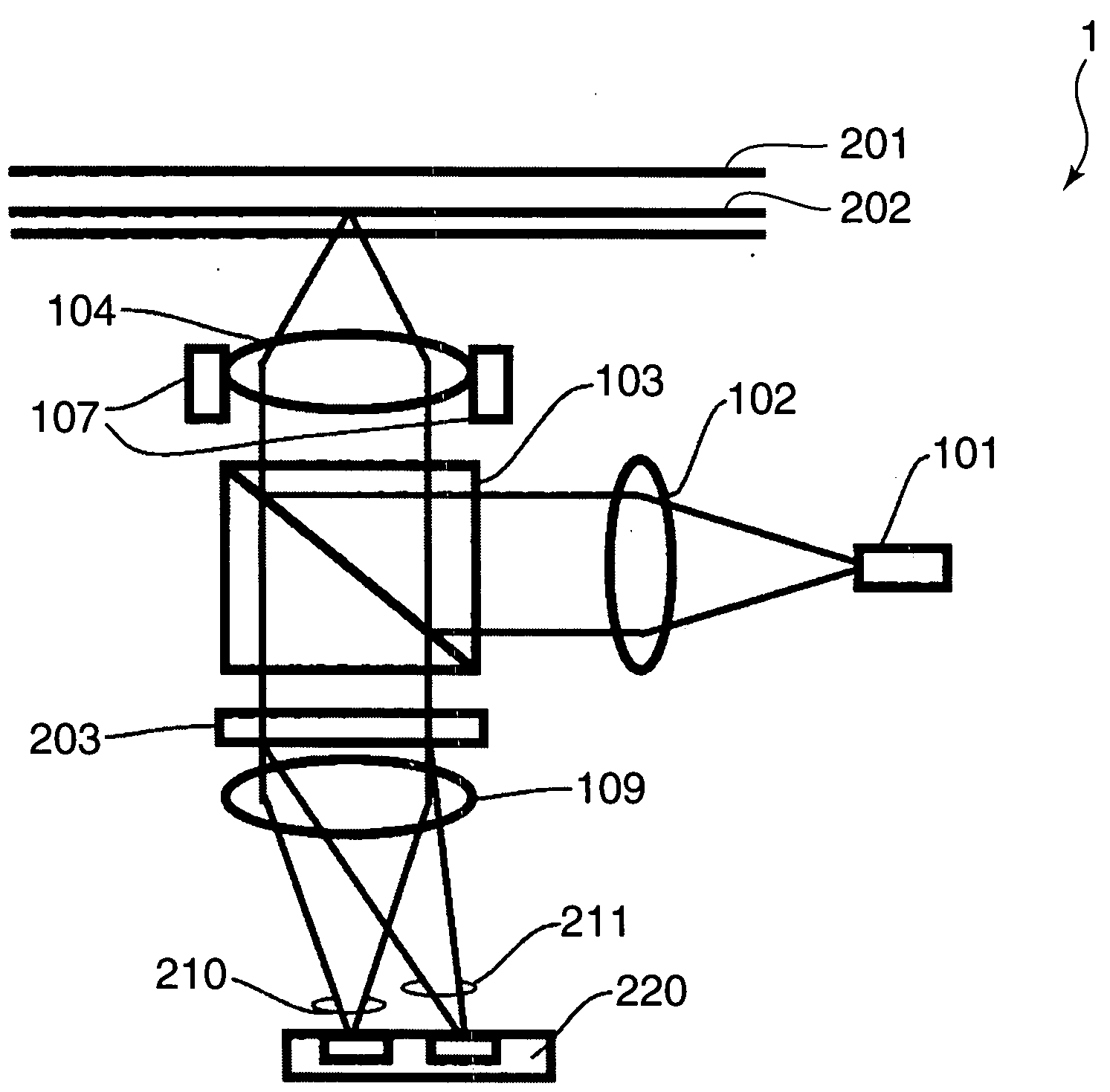
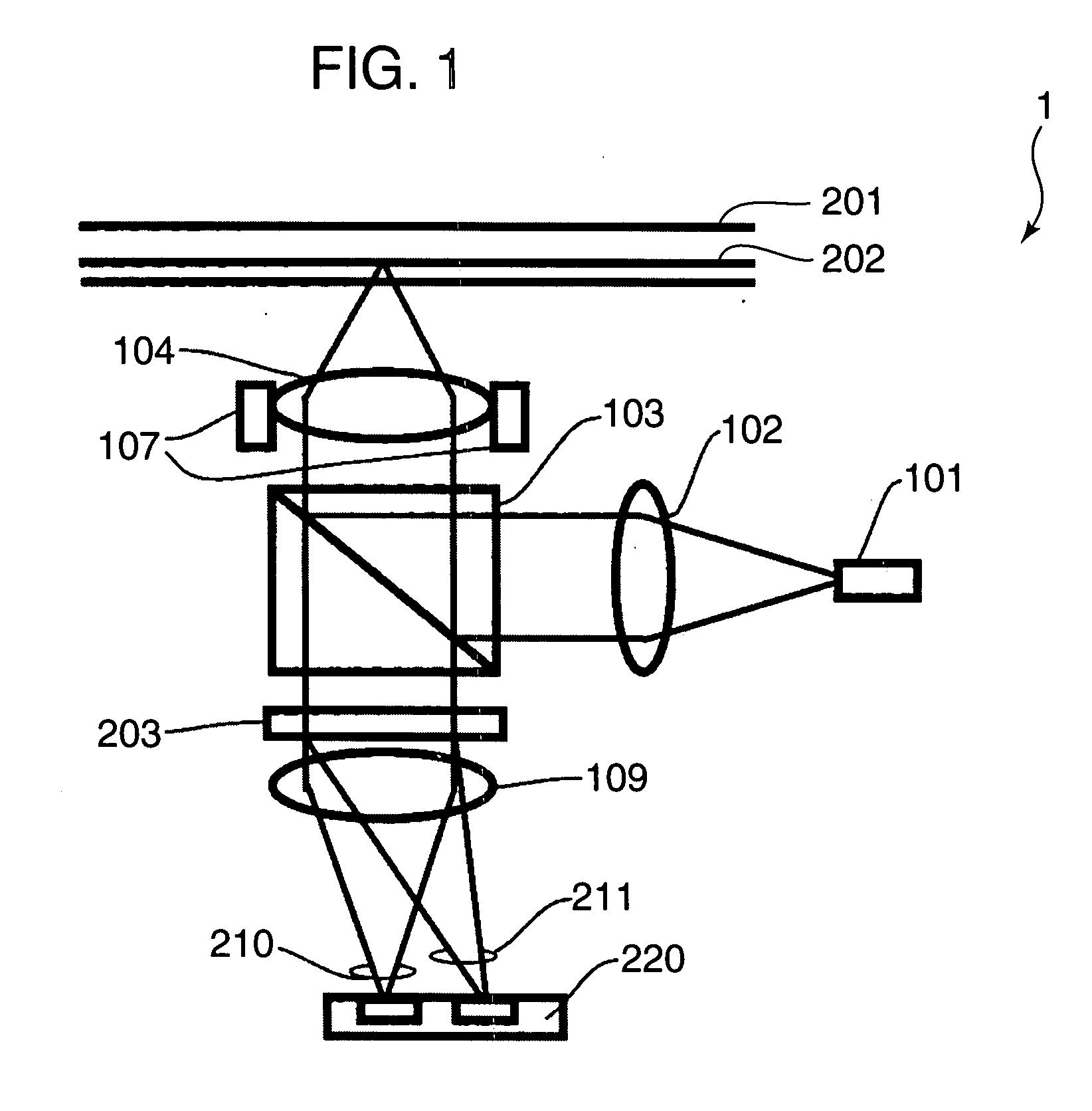
[0058]FIG. 1 is a diagram showing the construction of an optical head device 1 according to a first embodiment of the preset invention. In FIG. 1, the same component elements as in FIG. 36 are not described by being identified by the same reference numerals.

[0059]In FIG. 1, the optical head device 1 includes a semiconductor laser 101, a collimator lens 102, a beam splitter 103, an objective lens 104, an actuator 107, a holographic element 203, a detection lens 109 and a photodetector 220.

[0060]The semiconductor laser 101 emits a light beam. The collimator lens 102 converts the light beam emitted from the semiconductor laser 101 from a divergent light into a collimated light. The beam splitter 103 reflects the light beam converted into the collimated light by the collimator lens 102 toward an optical disc 201, and transmits the light beam reflected by the optical disc 201 toward the photodetector 220.

[0061]The objective lens 104 focuses the light beam reflected by the beam splitter 1...

second embodiment

[0111]In a second embodiment is described an example in which a diffraction direction of a light passing a central region is changed. FIG. 10 is a diagram showing a relationship between light receiving portions of a photodetector of an optical head device according to the second embodiment of the present invention and light beams. In the second embodiment, a holographic element different from the one in the first embodiment is used and the diffraction direction of the light passing the central region is changed in a direction different from the one in the first embodiment. Specifically, a light beam 266 diffracted by a central region 243 is diffracted in a direction (direction shown by an arrow Y7) normal to a direction bisecting an angle defined between a main region light receiving portion group 25b and a subregion light receiving portion group 25a with an optical axis 221 as an apex. Light beams diffracted in other regions are diffracted to the same positions as in the first embo...

third embodiment

[0114]Although information is recorded and / or reproduced by irradiating light beams to one type of an optical disc in the optical head devices according to the first and second embodiments, information is recorded and / or reproduced by irradiating light beams having different wavelengths to three types of optical discs such as CDs, DVDs and Blu-ray discs (hereinafter, abbreviated as “BDs”).

[0115]An optical head device capable of reproducing / writing with CDs, DVDs and high-density optical discs such as BDs includes light sources for emitting three lights having different wavelengths to reproduce information from the respective discs. In this case, the number of parts can be reduced by receiving these lights by one photodetector.

[0116]FIG. 12 is a diagram showing the construction of an optical head device according to a third embodiment. An optical head device 30 shown in FIG. 12 includes a first light source 11, a beam splitter 12, a relay lens 13, a holographic element 14, a dichroic...


PUM


Abstract

The present invention aims to generate an offset-free tracking signal and to realize a stable tracking control even if an optical disc is a multi-layer disc having three or more layers.
Light receiving portions of a main region light receiving portion group is arranged between a projection line of a third dividing line on a photodetector and a projection line of a fourth dividing line on the photodetector by stray lights from information layers adjacent to the one, on which a light beam is focused, out of a plurality of information layers. Further, light receiving portions of a subregion light receiving portion group is arranged between a projection line of a first dividing line on a photodetector and a projection line of a second dividing line on the photodetector by the stray lights from the information layers adjacent to the one, on which a light beam is focused, out of the plurality of information layers.

Description

BACKGROUND OF THE INVENTION[0001]1. Field of the Invention[0002]The present invention relates to an optical head device and an optical information device for recording and / or reproducing information on and / or from an information recording medium such as an optical disc or an optical card.[0003]2. Description of the Background Art[0004]In a conventional optical head device, a part of light reflected and diffracted from an optical disc as an information recording medium is diffracted and the diffracted light is detected by a light receiving portion different from the one for receiving a transmission light (0th-order light), which is not diffracted, and used as a tracking signal (see, for example, FIG. 25 of Japanese Unexamined Patent Publication No. 2004-281026). FIG. 36 is a diagram showing the construction of a conventional optical head device 100 disclosed in the prior art document.[0005]In FIG. 36, a light beam emitted from a semiconductor laser 101 is converted into a collimated ...

Claims


Application Information

Patent Timeline
IPC IPC(8): G11B7/00
CPCG11B7/0901G11B7/131G11B2007/0013G11B7/1381G11B7/1353
Inventor SANO, KOUSEINAGATA, TAKAYUKIAIKOH, HIDEKIANZAI, JOJIYAMASAKI, FUMITOMO
Owner PANASONIC CORP
Why Eureka
Try Eureka