

Optical disc device
An optical disc device and optical disc technology, which can be used in beam guiding devices, optical detectors, optical recording heads, etc., and can solve problems such as hindering track control
- Summary
- Abstract
- Description
- Claims
- Application Information
AI Technical Summary
Problems solved by technology
Method used
Image

Examples
Embodiment Construction
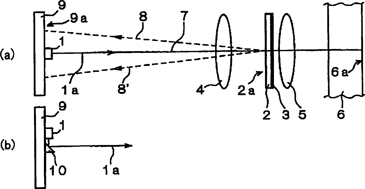
[0037] Refer below Figure 1 to Figure 6 An optical disc device according to one embodiment of the present invention will be described in detail. In addition, the same reference numerals are attached to the same components as those of the above-mentioned conventional optical disc device.
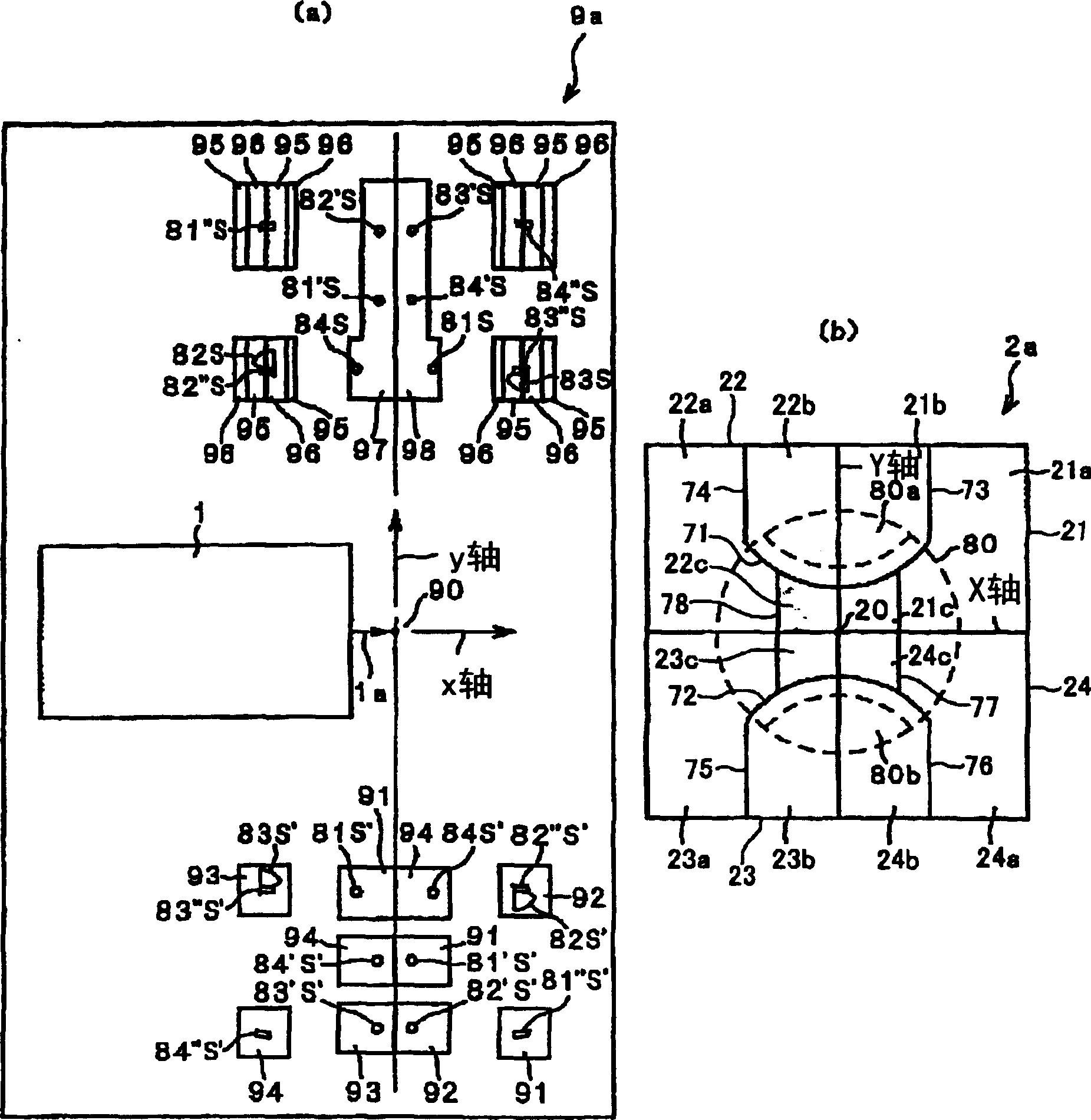
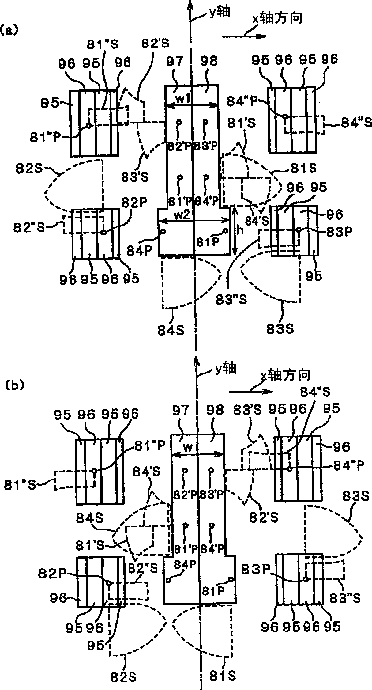
[0038] The optical disc device of this embodiment and figure 1 The optical disc device of the prior art shown has a photodetection substrate 9 and a light source 1 mounted on the photodetection substrate 9 . The light source 1 is, for example, a semiconductor laser or the like. And, this optical disc device is the same as the optical disc device of the prior art, and has collimating lens 4, polarizing holographic substrate 2, 1 / 4 wavelength plate 3 and objective lens 5 on the optical path of the laser light 1a emitted from light source 1. 1 / 4 The wave plate 3 is provided on the back surface of the polarizing hologram substrate 2 . However, the domain structure of the hologram surface 2a ...
PUM
 Abstract
Description
Claims
Application Information