
Moving magnetic field generating apparatus

a technology of moving magnetic field and generating apparatus, which is applied in the direction of magnetism, instruments, greenhouse gas reduction, etc., can solve the problem that the moving magnetic field generating apparatus cannot generate a high-speed magnetic field

Inactive Publication Date: 2012-03-29
SANYO DENKI CO LTD
View PDF4 Cites 8 Cited by
  • Summary
  • Abstract
  • Description
  • Claims
  • Application Information

AI Technical Summary

Benefits of technology

[0006]An object of the present invention is to provide a moving magnetic field generating apparatus capable of generating a high speed moving magnetic field that moves at a speed higher than that of the conventional moving magnetic field generating apparatus.
[0009]According to the moving magnetic field generating apparatus of the present invention, a high-speed moving magnetic field can be easily formed by the synthesized magnetic flux that moves at a speed faster than the relative moving speed.
[0014]In a further aspect of the present invention, an electric apparatus, such as a linear electric motor, a rotary electric motor, a rotary electric generator, or a linear electric generator, is provided to include: the moving magnetic field generating apparatus according to the present invention; and a magnetic pole array including a plurality of coils disposed at a predetermined pitch to form a plurality of magnetic poles. The coils in the magnetic pole array are disposed to face at least one of the first and second magnetic pole piece arrays of the moving magnetic field generating apparatus. In the conventional rotary electric motor, if the wire diameter of the winding is increased to reduce a copper loss, a large slot area is required and the magnetic resistance is increased, which may saturate the maximum thrust. In the rotary electric motor which utilizes the moving magnetic field generating apparatus according to the present invention, in contrast, a coil space factor or the space occupied by the winding can be increased without significantly varying the magnetic resistance even if the number of turns or the wire diameter of the winding is increased. Thus, the rated thrust density and the maximum thrust per size can be increased, thereby providing a high-efficiency rotary electric motor that can contribute to energy conservation. In the conventional electric generator, a speed increasing gear is used to rotate the generator at a high speed in order to allow an operation in a range where a high efficiency is achieved, that is, in a high-speed range. However, the gear has a limited life and may be broken, presenting issues to be addressed in terms of cost and maintenance. In addition, the gear may have a complicated configuration, hindering a reduction in the size of the generator. In the electric generator which uses the moving magnetic field generating apparatus according to the present invention, in contrast, the rotational speed of the synthesized magnetic field is high compared to the rotational speed of the rotor. Therefore, a high voltage is induced to enable high-efficiency power generation even when the rotational speed of the rotor is low. Thus, a speed increasing gear can be dispensed with, contributing to facilitating maintenance and achieving a size reduction and a high efficiency. A linear electric generator extending linearly may also be formed by utilizing the moving magnetic field generating apparatus according to the present invention.

Problems solved by technology

The conventional moving magnetic field generating apparatus is incapable of generating a magnetic field that moves at a high speed.

Method used


Image

  • Moving magnetic field generating apparatus
  • Moving magnetic field generating apparatus
  • Moving magnetic field generating apparatus

Examples


Embodiment Construction

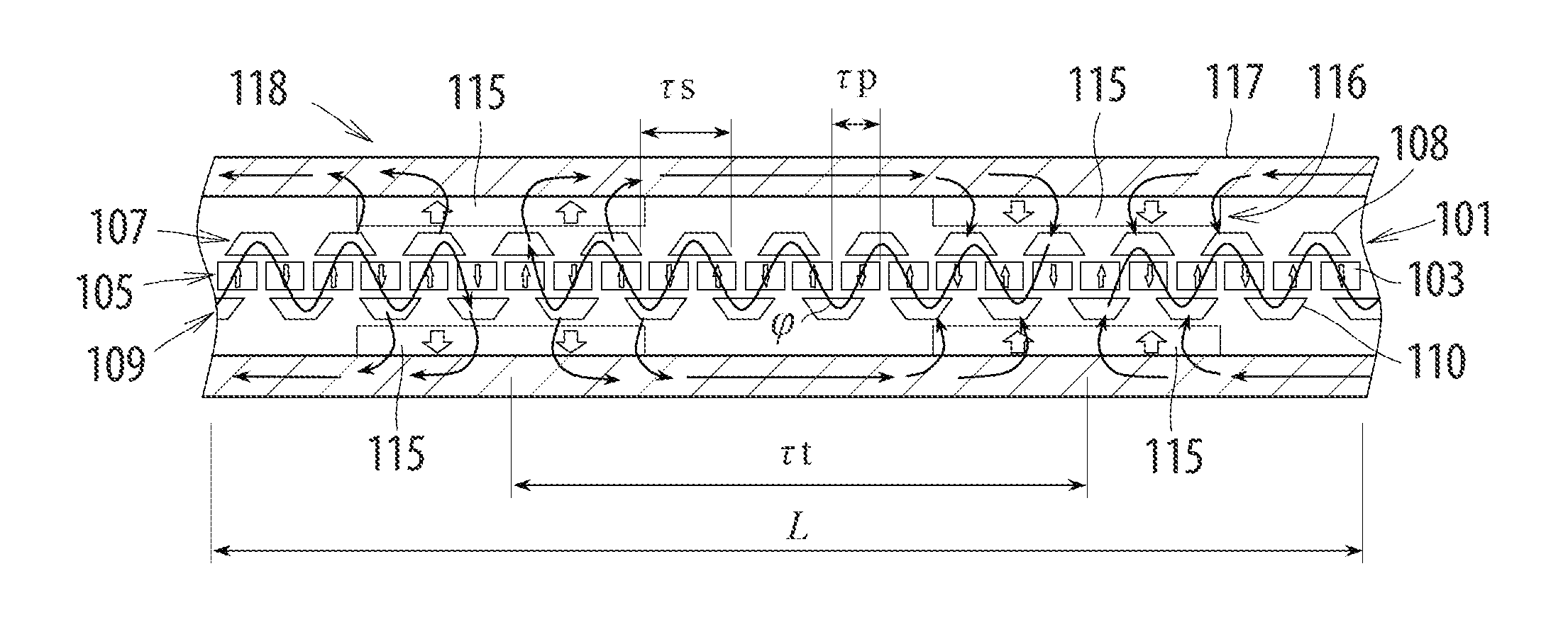
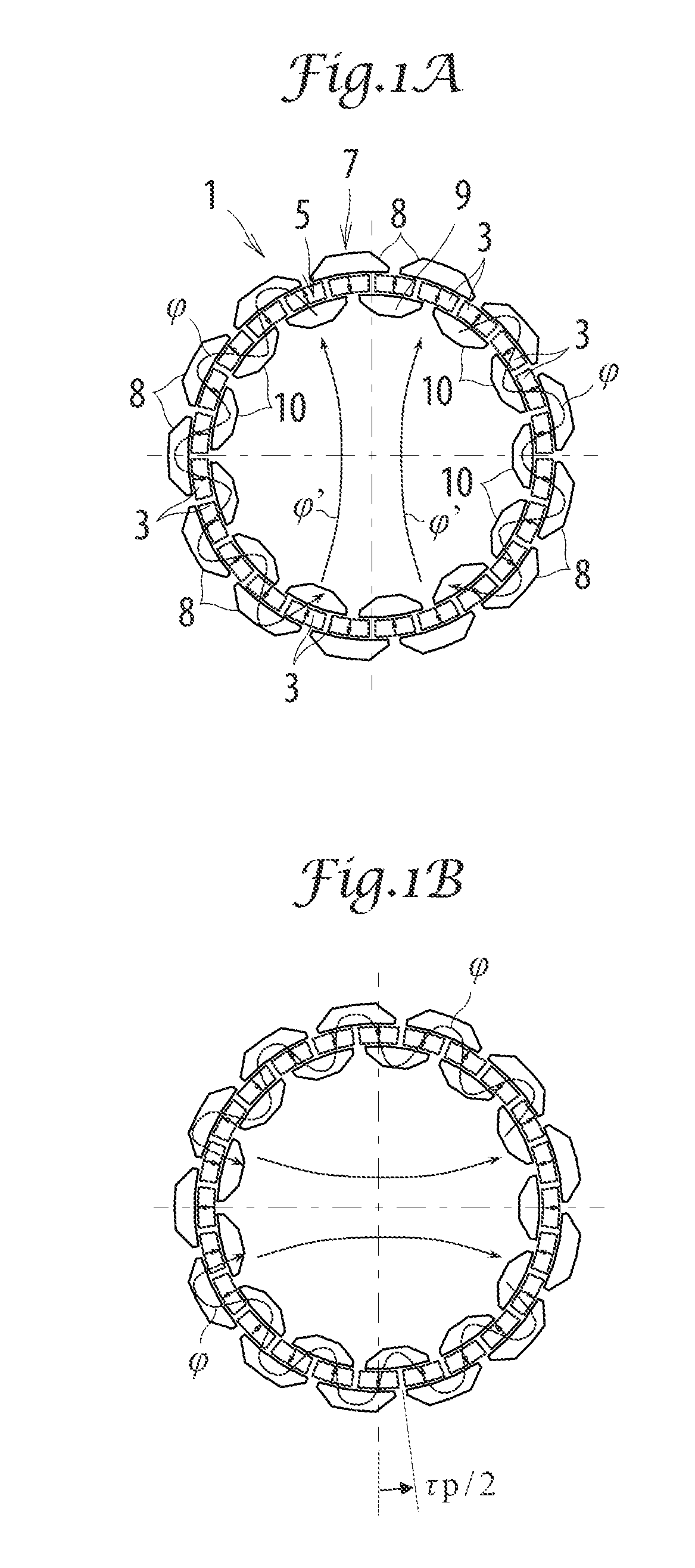
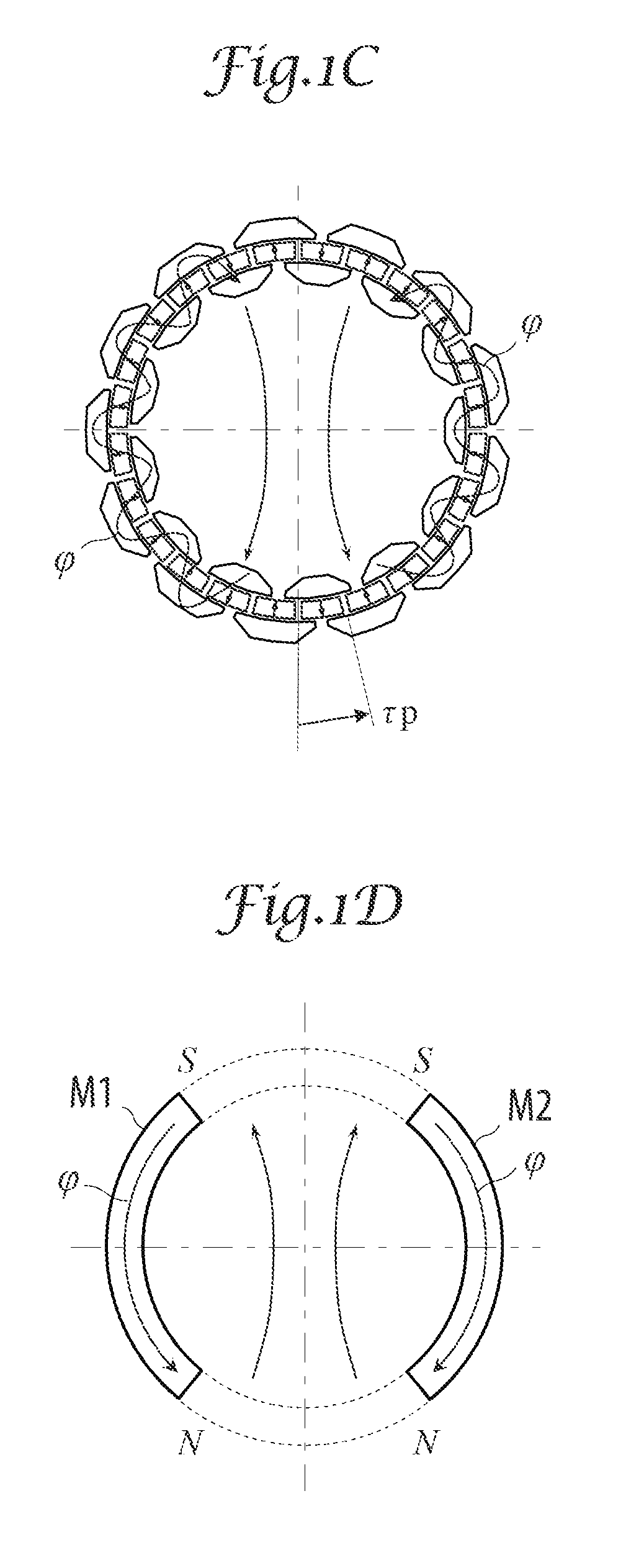
[0042]An embodiment of a moving magnetic field generating apparatus according to the present invention and embodiments of various apparatuses configured to utilize the moving magnetic field generating apparatus will be described with reference to the drawings. FIGS. 1A to 1C show the configuration of a rotary moving magnetic field generating apparatus according to the present invention and the flow of synthesized magnetic flux generated by the rotary moving magnetic field generating apparatus, and FIGS. 1D to 1F schematically show synthesized magnetic poles formed by the synthesized magnetic flux in FIGS. 1A to 1C. A rotary moving magnetic field generating apparatus 1 according to the embodiment includes an annular magnet array 5 including 2N (specifically, 24) magnets 3 disposed at a first pitch τp such that N and S poles of adjacent magnets 3 in the magnet array 5 are alternated, and first and second annular magnetic pole piece arrays 7 and 9 extending along the magnet array 5 to ...


PUM


Abstract

A moving magnetic field generating apparatus includes a magnet array including magnets disposed at a first pitch such that N and S poles of adjacent magnets in the magnet array are alternated, and first and second magnetic pole piece arrays extending along the magnet array to interpose the magnet array therebetween with a gap from the magnet array. The first and second magnetic pole piece arrays are disposed with a predetermined phase difference therebetween. The first magnetic pole piece array includes first magnetic pole pieces disposed at a second pitch in an array and each having a length enough to face at least two adjacent magnets in the magnet array. The second magnetic pole piece array is configured similarly to the first magnetic pole piece array. One of the first and second magnetic pole piece arrays and the magnet array is relatively moved to the other at a predetermined speed.

Description

BACKGROUND OF THE INVENTION[0001]1. Technical Field[0002]The present invention relates to a moving magnetic field generating apparatus, and to an apparatus configured to utilize a high-speed moving magnetic field generated by the moving magnetic field generating apparatus.[0003]2. Description of the Related Art[0004]Japanese Patent No. 3452709 discloses a moving magnetic field generating apparatus configured to generate a moving magnetic field for use in continuous casting.[0005]The conventional moving magnetic field generating apparatus is incapable of generating a magnetic field that moves at a high speed.SUMMARY OF THE INVENTION[0006]An object of the present invention is to provide a moving magnetic field generating apparatus capable of generating a high speed moving magnetic field that moves at a speed higher than that of the conventional moving magnetic field generating apparatus.[0007]Another object of the present invention is to provide an apparatus configured to utilize a hi...

Claims


Application Information

Patent Timeline
IPC IPC(8): H02K49/10H02K7/10F03D9/00H02K7/02H02K7/11G01B7/30
CPCH02K44/00H02K49/102H02K2213/03H02K7/1838H02K16/02H02K21/12H02K7/025Y02E10/725F03D9/002G01B7/30H01F7/202H02K1/2786H02K41/031F03D9/25F03D9/12Y02E60/16Y02E10/72Y02E70/30H02K1/2791H05H1/30
Inventor SUGITA, SATOSHIMISAWA, YASUSHITANG, YUQIMIYAIRI, SHIGENORI
Owner SANYO DENKI CO LTD
Learn More