Overlapping type freezing-force circulation refrigeration unit (high pressure side)

a refrigeration unit and circulation technology, applied in the field of refrigeration technology, can solve the problems of not being able to build a continuous power machine, not being able to explain the refrigerating cycle in simple, clear and intuitional terms, and not being able to meet the requirements of continuous power generation

Active Publication Date: 2016-03-24
NANJING RECLAIMER ENVIRONMENTAL TEKNIK
View PDF0 Cites 2 Cited by
  • Summary
  • Abstract
  • Description
  • Claims
  • Application Information

AI Technical Summary

Problems solved by technology

1) Researches on methods to obtain low temperature, the relevant mechanisms and the corresponding refrigerating cycles, and thermodynamic analysis and calculation of refrigerating cycles.
2) Researches on the properties of refrigerants, to provide refrigerators with media having satisfactory performance. Mechanical refrigeration can be realized by changing the thermodynamic status of refrigerant, therefore, the thermal physical property of refrigerant is the basis for cycle analysis and calculation. Furthermore, for the practical application of refrigerants, their general physical and chemical properties must also be well known.
3) Researches on the machinery and technical equipment required to realize refrigerating cycles, their working principles, performance analysis, structural design and calculation, and the flow organization and system associated calculation for various refrigeration apparatuses. In addition, there are questions about thermal insulation and automation of refrigerating equipment and so on.
1) The thermal efficiency of Carnot cycle only depends on the temperature of high temperature heat source and low temperature heat source, or the temperature at which the media absorbs heat and release heat, therefore the thermal efficiency can be increased by increasing T1 and decreasing T2.
2) The thermal efficiency of Carnot cycle can only be less than 1, and can never be equal to 1, because it is not possible to realize T1=∞ or T2=0. This means that a cyclic engine, even under an ideal condition, cannot convert all thermal energy into mechanical energy, of course, it is even less possible that the thermal efficiency is greater than 1.
3) When T1=T2, the thermal efficiency of the cycle is equal to 0, it indicates that in a system of balanced temperature, it is not possibl

Method used


Image

  • Overlapping type freezing-force circulation refrigeration unit (high pressure side)
  • Overlapping type freezing-force circulation refrigeration unit (high pressure side)
  • Overlapping type freezing-force circulation refrigeration unit (high pressure side)

Examples


Embodiment Construction

[0076]To facilitate understanding by technical personnel in the field, the invention is further described in the following in conjunction with figures.

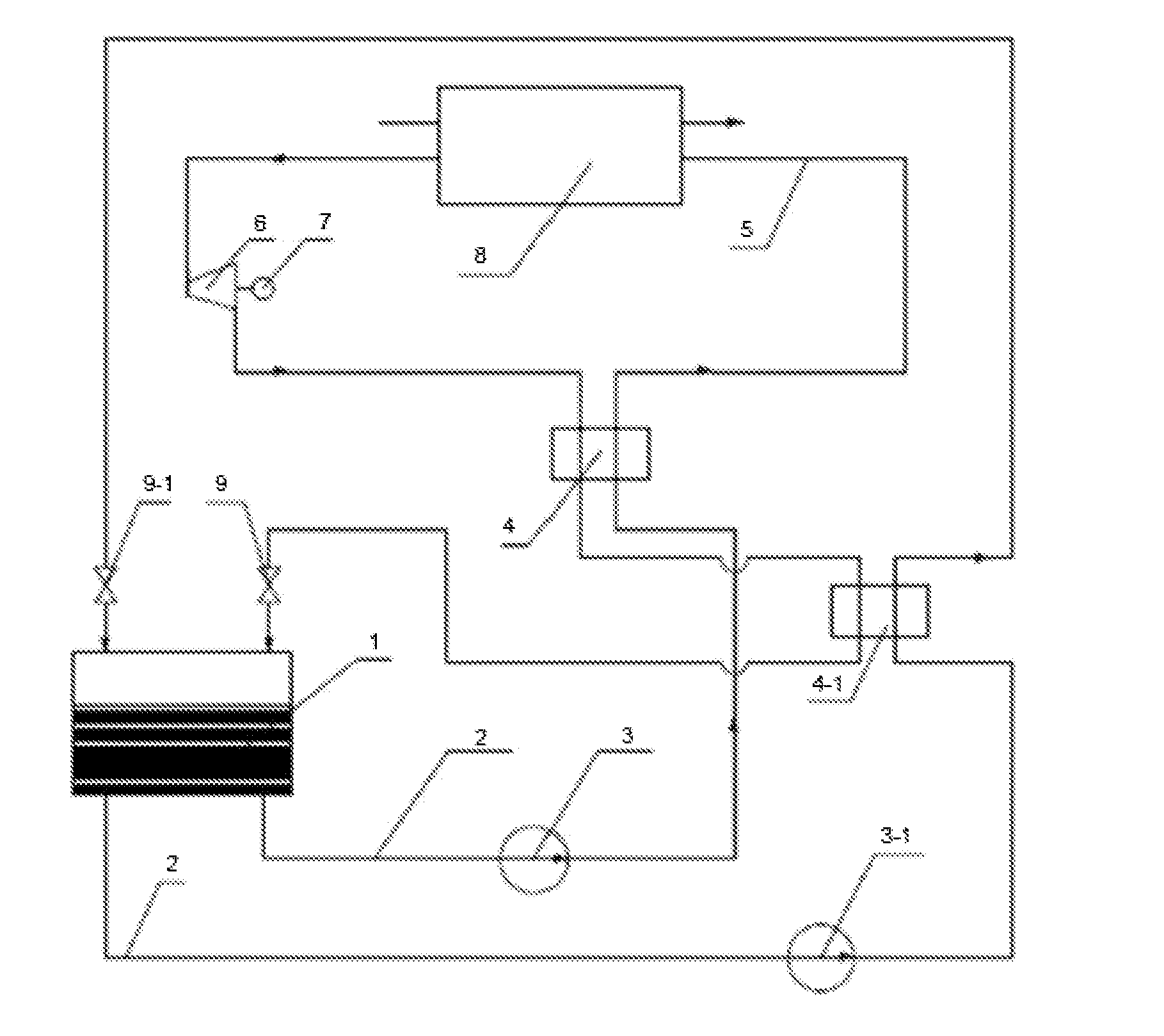
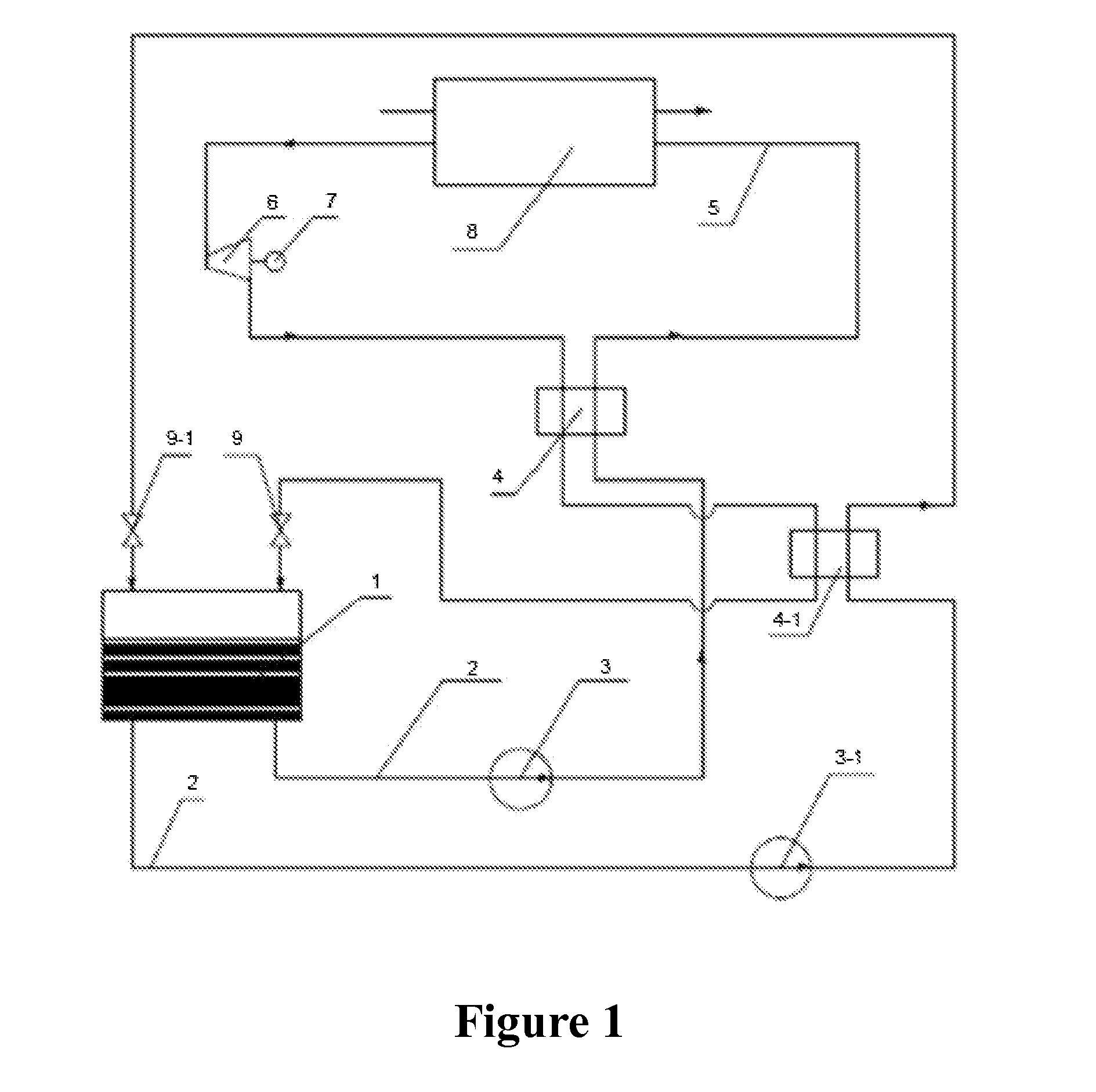
[0077]As shown in FIG. 1, a cold dynamic cycle refrigeration apparatus, with the specific embodiment as follows:

[0078]Liquid nitrogen is used as refrigerant.

[0079]The liquid refrigerant 2 from refrigerant tank 1, after being boosted via liquid circulating pump 3, flows via cold regenerator 4, cold consuming apparatus 8, and expander 6 to drive the braking equipment 7, the exhaust vapor from expander 6 flows again via cold regenerator 4, cold regenerator 4-1 and throttle valve 9, and returns to the refrigerant tank 1; the liquid refrigerant 2 from refrigerant tank 1, after being boosted by the liquid circulating pump 3-1, flows via the cold regenerator 4-1 and throttle valve 9-1, and returns to the refrigerant tank 1, so as to form the cascade cold dynamic cycle circuit of the refrigerating media.

[0080]The said cold consuming apparatus...


PUM


Abstract

This invention is about a cascade cold dynamic cycle refrigeration apparatus, which makes up cold energy with cryogenic liquid refrigerant by boosting with a dual-stage liquid circulating pump, after its temperature is increased via the cold regenerator, it enters the cold consuming apparatus to provide cold and becomes a gaseous refrigerant, then it flows through the expander to expand and make work by reducing pressure and temperature, and then returns to the refrigerant tank via the cold regenerator or/and throttle valve. This invention requires no circulation cooling water system as in a traditional vapor compression refrigeration apparatus, so its maintenance and operation cost can be substantially reduced, with a apparatus of the same refrigerating capacity, it can save energy by more than 30% as compared with traditional ones, as compared with traditional refrigerating circulation technology, it can adopt enhanced cold transfer elements more conveniently, with more compact refrigerating equipment and higher refrigerating efficiency.

Description

TECHNICAL FIELD[0001]This invention falls into the refrigerating technology field, specifically it is about a cascade cold dynamic cycle refrigeration apparatus.BACKGROUND OF THE INVENTION[0002]Modern refrigeration technology, as a science, was developed in the mid and late 19th century, before that, tracing back to the ancestors of the human being, people learned very long ago to make use of cold and make simple manual refrigeration, and using cellars and cold store and cooling a store room with spring water have a history of 5000 years.[0003]The 20th century saw greater development of refrigeration technologies: the household refrigerator was born in 1910, and was marketed as a commodity in the United States in 1917. In 1930, the appearance of Freon refrigerating media and the use of Freon refrigerators brought new transformation to the refrigeration technologies. In the 1970s, massive researches were conducted on mixed media, and co-boiling mixed media were used, ushering a new r...

Claims


Application Information

Patent Timeline
IPC IPC(8): F25B23/00F01K13/00
CPCF01K13/00F25B23/00F25B23/006F01K25/08F25B11/02F25B2400/14F01K27/00
Inventor WANG, HAIBOLIU, LAIKOULIANG, BINDING, LIN
Owner NANJING RECLAIMER ENVIRONMENTAL TEKNIK
Why Eureka
Try Eureka