Wire Treatment Pliers Set

a technology of wire treatment and pliers, which is applied in the direction of multi-purpose tools, line/current collector details, electric cable installation, etc., can solve the problems of inconvenient carrying and storage of many tools, high cost of users buying tools of different specifications,

Inactive Publication Date: 2016-06-23
HANLONG INDAL
View PDF5 Cites 9 Cited by
  • Summary
  • Abstract
  • Description
  • Claims
  • Application Information

AI Technical Summary

Benefits of technology

The present invention provides a wire treatment pliers set that has various wire processing functions for your convenience. This means that this tool can be used for different purposes without requiring other tools or equipment.

Problems solved by technology

The technical problem addressed in this patent text is the difficulty and expense of purchasing and carrying various tools to process different types of wires and signals used in electronic devices due to their varying sizes and specifications. There is also a lack of efficiency when connecting these devices because they often require different tools for different parts of the connection process. A solution is needed to simplify the wire processing task while providing versatility and ease-of-use.

Method used


Image

  • Wire Treatment Pliers Set
  • Wire Treatment Pliers Set
  • Wire Treatment Pliers Set

Examples


Embodiment Construction

[0028]These and other objects and advantages of the present invention will become apparent from the following description of the accompanying drawings, which disclose several embodiments of the present invention. It is to be understood that the drawings are to be used for purposes of illustration only, and not as a definition of the invention.

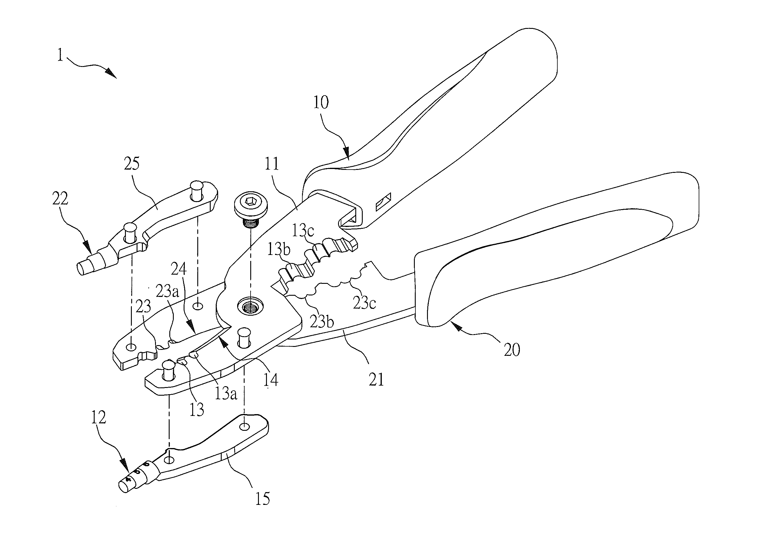
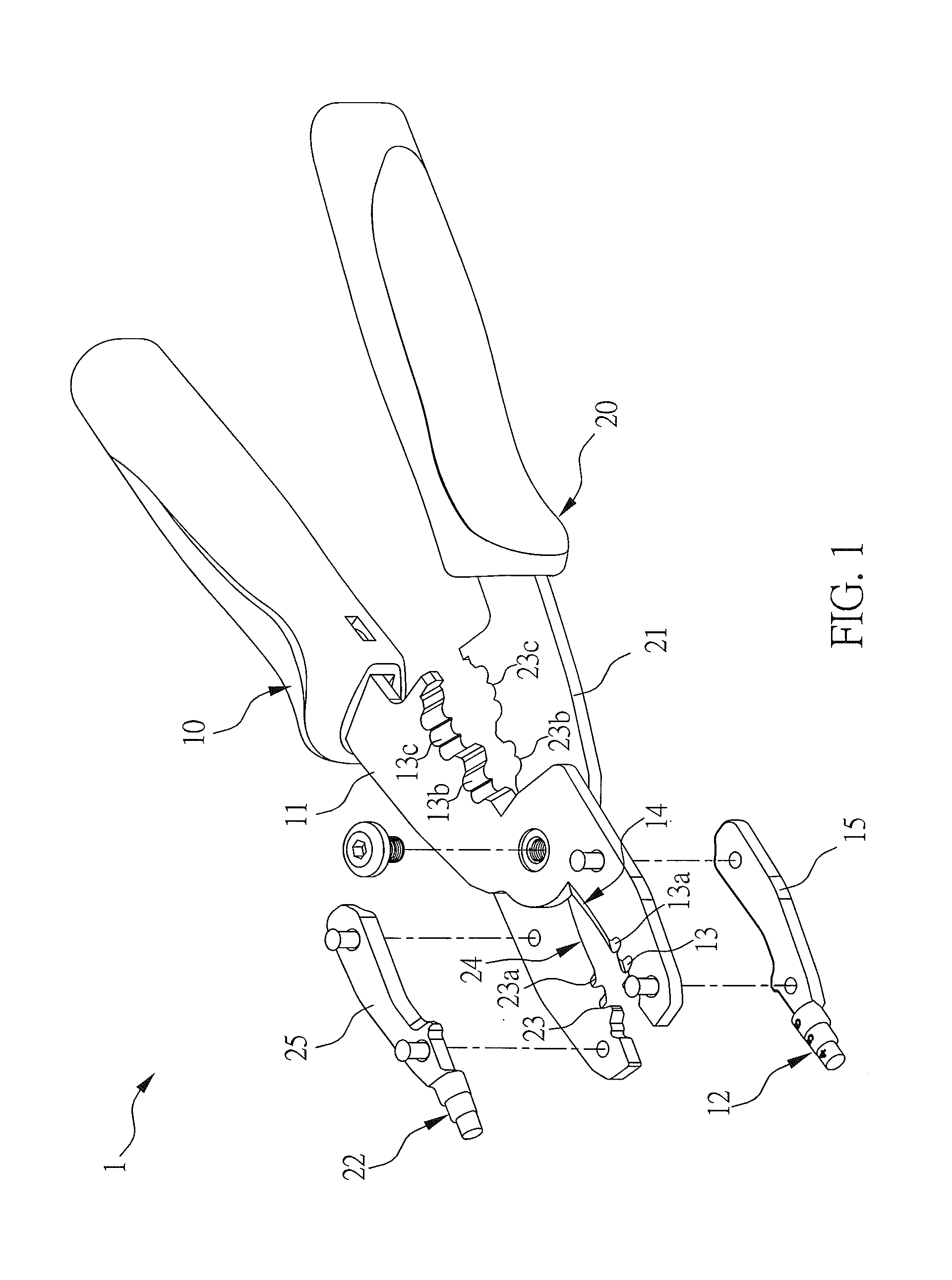
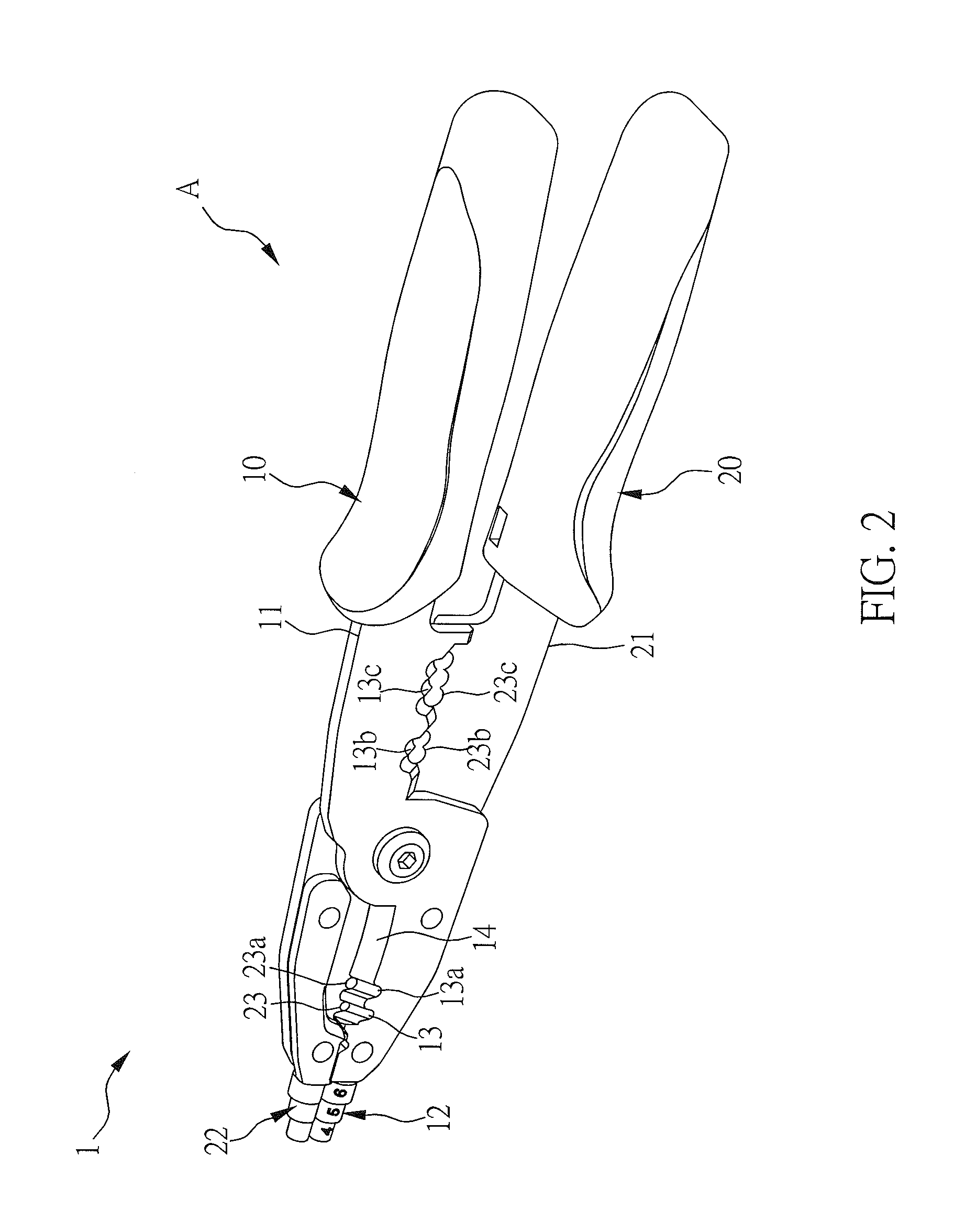
[0029]Please refer to FIG. 1 to FIG. 8 about the wire treatment pliers set in the first embodiment of the present invention. FIG. 1 illustrates an exploded perspective view of the wire treatment pliers set in the first embodiment of the present invention. FIG. 2 illustrates a schematic drawing of the wire treatment pliers set in a closed state in the first embodiment of the present invention. FIG. 3 illustrates a schematic drawing of the wire treatment pliers set in an open state in the first embodiment of the present invention. FIG. 4 illustrates a partial schematic drawing of the wire treatment pliers set in the first embodiment of the presen...


PUM


Abstract

A wire treatment pliers set includes a first clamp body and a second clamp body. The first clamp body includes a first main body, a first winding part and at least one first stripping notch. The at least one first stripping notch is located on the first main body. The second clamp body is pivotally connected to the first clamp body. The second clamp body includes a second main body, a second winding part, and at least one second stripping notch. A position of the second winding part corresponds to the first winding part. The at least one second stripping notch is located on the second main body, and a position of the at least one second stripping notch corresponds to the at least one first stripping notch.

Description


Claims


Application Information

Patent Timeline
Owner HANLONG INDAL
Why Eureka
Try Eureka