This helps you quickly interpret patents by identifying the three key elements:
Problems solved by technology
Method used
Benefits of technology
Benefits of technology
[0007]One aspect of the present disclosure involves a heater base for supplying humidified gases to a patient or user. The heater base comprises a base portion. The base portion comprises a recessed region. A heater plate is positioned in the recessed region. The heater plate is configured to contact a heat conductive portion of a removable hum
Problems solved by technology
The second spring assembly platform includes an opening is large enough to allow the screw body to pass thro
Method used
Image
Click on the blue label to locate the original text in one second.
Reading with bidirectional positioning of images and text.
Examples
example operational modes
and Features
[0250]FIGS. 30A-C illustrate flow charts of an example operational method 3000 of a humidification system wherein the method is configured to detect when a breathing circuit is connected improperly, such as when the breathing circuit is connected and provides a flow the reverse of a normal flow. In some embodiments, the operational method can also be configured to detect when there is no flow due to a portion of the breathing circuit being disconnected. A reverse flow can be when the flow of air is reverse to the normal flow of air under normal operating circumstances, such as when an expiratory conduit is coupled to an output of a blower or ventilator, a dry line is coupled from an inlet port of a chamber to an inlet of the blower or ventilator, and an inspiratory conduit is coupled from a patient interface to an outlet port of the chamber. For ease of description, the steps of the method 3000 will be described as being performed by the humidification system, such as th...
PUM
Abstract
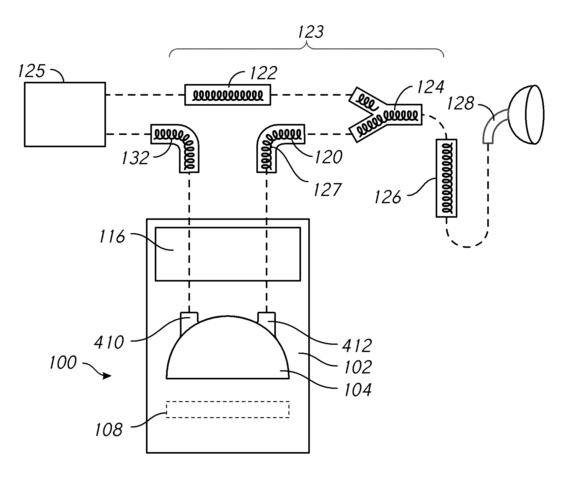
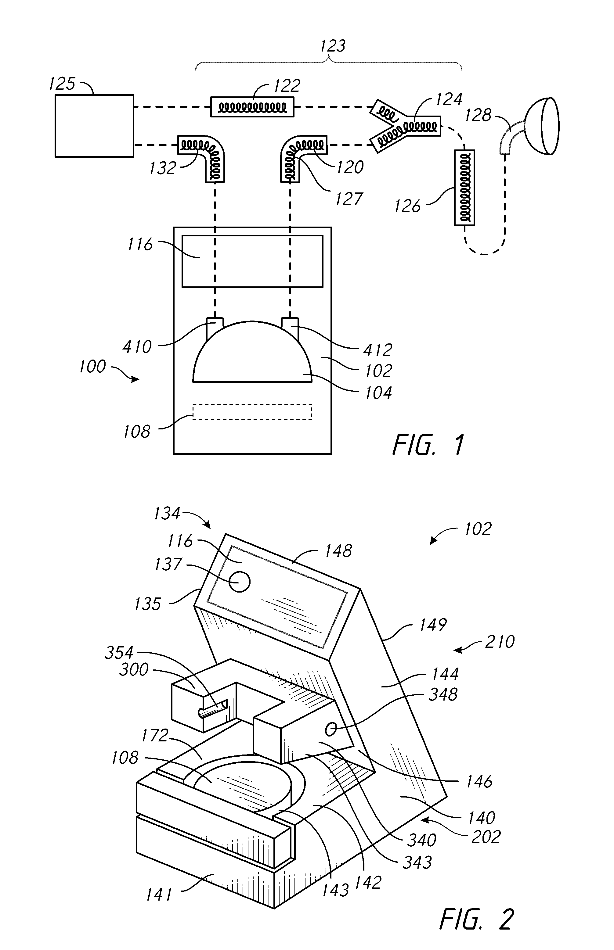
A humidification system can include a heater base, a chamber, and a breathing circuit. The heater base includes a heater plate positioned in a recessed region, and a heat conductive portion of the chamber is configured to contact the heater plate. The heater base includes a guard configured to control movement of the chamber into and out of the recessed region. The guard includes an anti-racking mechanism. The chamber includes an inlet port, an outlet port. A downward extension extends into the chamber from the inlet port, and a baffle is disposed at a lower end of the downward extension. A component of the breathing circuit can include a conduit hanging end cap for shipping and storage. The end cap can include a hanging component to allow the breathing circuit component to be hung from a medical stand. The system can detect when breathing circuits are connected in reverse.
Description
INCORPORATION BY REFERENCE[0001]Any and all applications for which a foreign or domestic priority claim is identified in the Application Data Sheet as filed with the present application are hereby incorporated by reference under 37 CFR 1.57.[0002]The following provisional applications are hereby incorporated by reference in their entirety: the U.S. Provisional Application having the title HUMIDIFICATION SYSTEM and Attorney Docket No.: FPHCR.371PR2 and Ser. No. 62 / 032,462, filed on Aug. 1, 2014; U.S. Provisional Application having the title CONNECTIONS FOR HUMIDIFICATION SYSTEM and Attorney Docket No.: FPHCR.371PR and Ser. No. 61 / 877,566, filed on Sep. 13, 2013; the U.S. Provisional Application having the title MEDICAL TUBES AND METHODS OF MANUFACTURE and Attorney Docket No.: FPHCR.273PR5 and Ser. No. 61 / 877,622, filed on Sep. 13, 2013; the U.S. Provisional Application having the title ZONE HEATING FOR RESPIRATORY CIRCUITS and Attorney Docket No.: FPHCR.335PR3 and Ser. No. 61 / 877,736...
Claims
Application Information
Patent Timeline
Application Date:The date an application was filed.
Publication Date:The date a patent or application was officially published.
First Publication Date:The earliest publication date of a patent with the same application number.
Issue Date:Publication date of the patent grant document.
PCT Entry Date:The Entry date of PCT National Phase.
Estimated Expiry Date:The statutory expiry date of a patent right according to the Patent Law, and it is the longest term of protection that the patent right can achieve without the termination of the patent right due to other reasons(Term extension factor has been taken into account ).
Invalid Date:Actual expiry date is based on effective date or publication date of legal transaction data of invalid patent.
Inventor JACKSON, JOHN JAMESMANON, BARRY SHACKCORRALES, VICTOR ROSALESVAN WORKUM, STEFAN LEOANDRESEN, MICHAEL JOHNEVANS, STEPHEN DAVIDHAMILTON, MARK SAMUELBUCKLEY, PAUL FLEMINGKLENNER, JASON ALLANOSBORNE, HAMISHBOGGS, SAMUEL GRAHAMSTANTON, JAMES WILLIAMGRIFFITHS, JOSEPH NATHANIELLAMBERT, JONATHAN ANDREW GEORGEVAUGHAN, NICHOLAS EDWARDKEHOE, JAMES OWENDE LA FUENTE, FRANCISCO ERNESTO DE LA PENAMCKENNA, NICHOLAS JAMES MICHAELPORTER, RACHAELSTAM, SIMON MORDECHAIKEMPS, DAVID ROBERTLYONS, EDWIN JOSEPHMARTIN, MADELEINE BESSSHOU, ADA YIWENLIU, HUANG-KU
