Components for breathing circuits

a technology of components and circuits, applied in respirators, other domestic articles, medical devices, etc., can solve problems such as condensation on the inside wall of conduits, and achieve the effects of reducing the adverse effect of condensation, reducing the condensation level, and reducing the formation of condensation

Pending Publication Date: 2017-10-19
FISHER & PAYKEL HEALTHCARE LTD
View PDF18 Cites 15 Cited by
  • Summary
  • Abstract
  • Description
  • Claims
  • Application Information

AI Technical Summary

Benefits of technology

[0004]It is an object of the present invention to provide a component, with particular application to the expiratory limb of a breathing circuit, which will at least go some way towards improving on the above or which will at least provide the public and the medical profession with a useful choice.
[0008]a short length of breathing conduit for connecting at one end to a patient interface component and at the other end to, directly or indirectly, the dual arms of a breathing circuit,

Problems solved by technology

Buildup of condensation on the inside wall of the conduit is a frequent result of this high humidity.

Method used


Image

  • Components for breathing circuits
  • Components for breathing circuits
  • Components for breathing circuits

Examples


Embodiment Construction

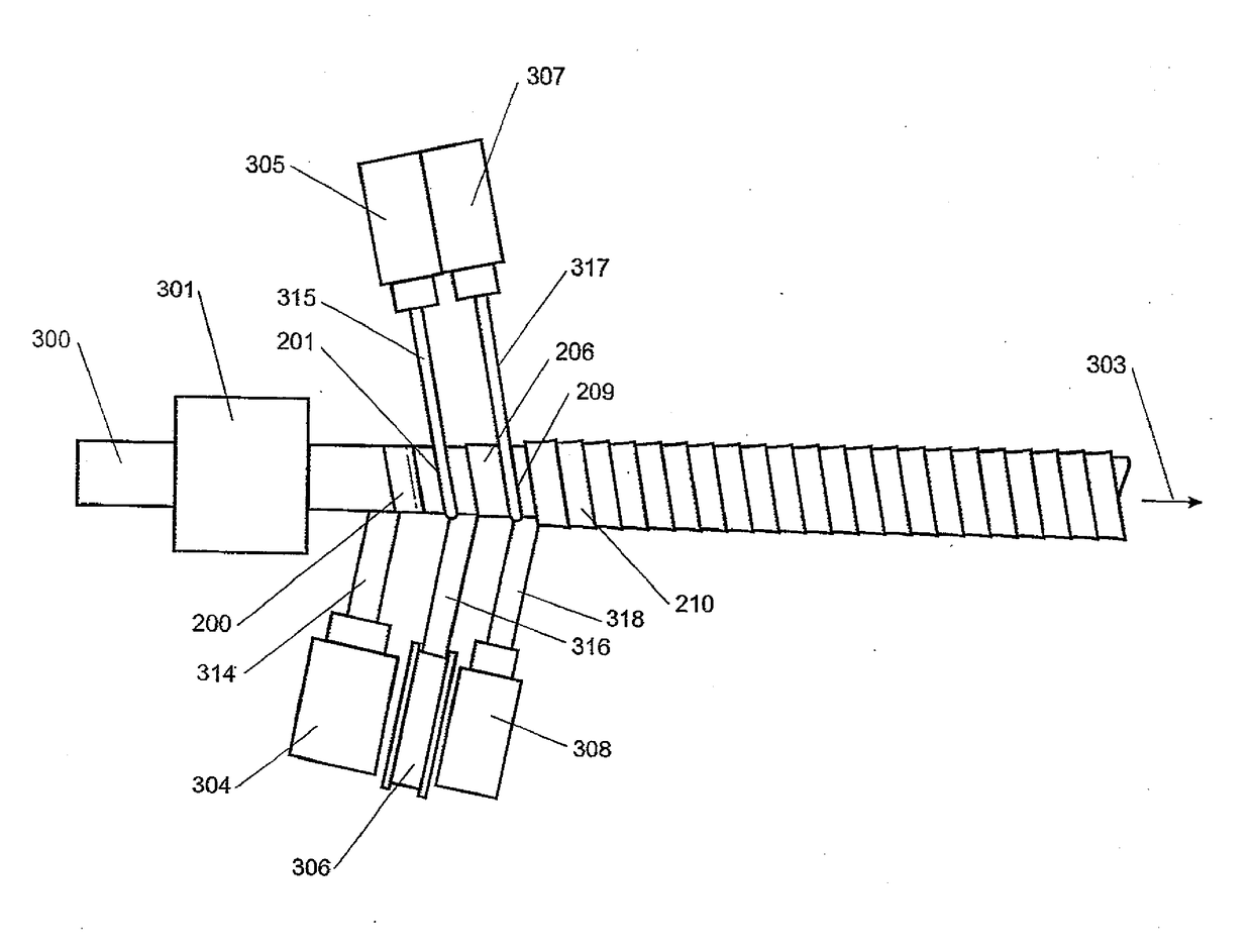
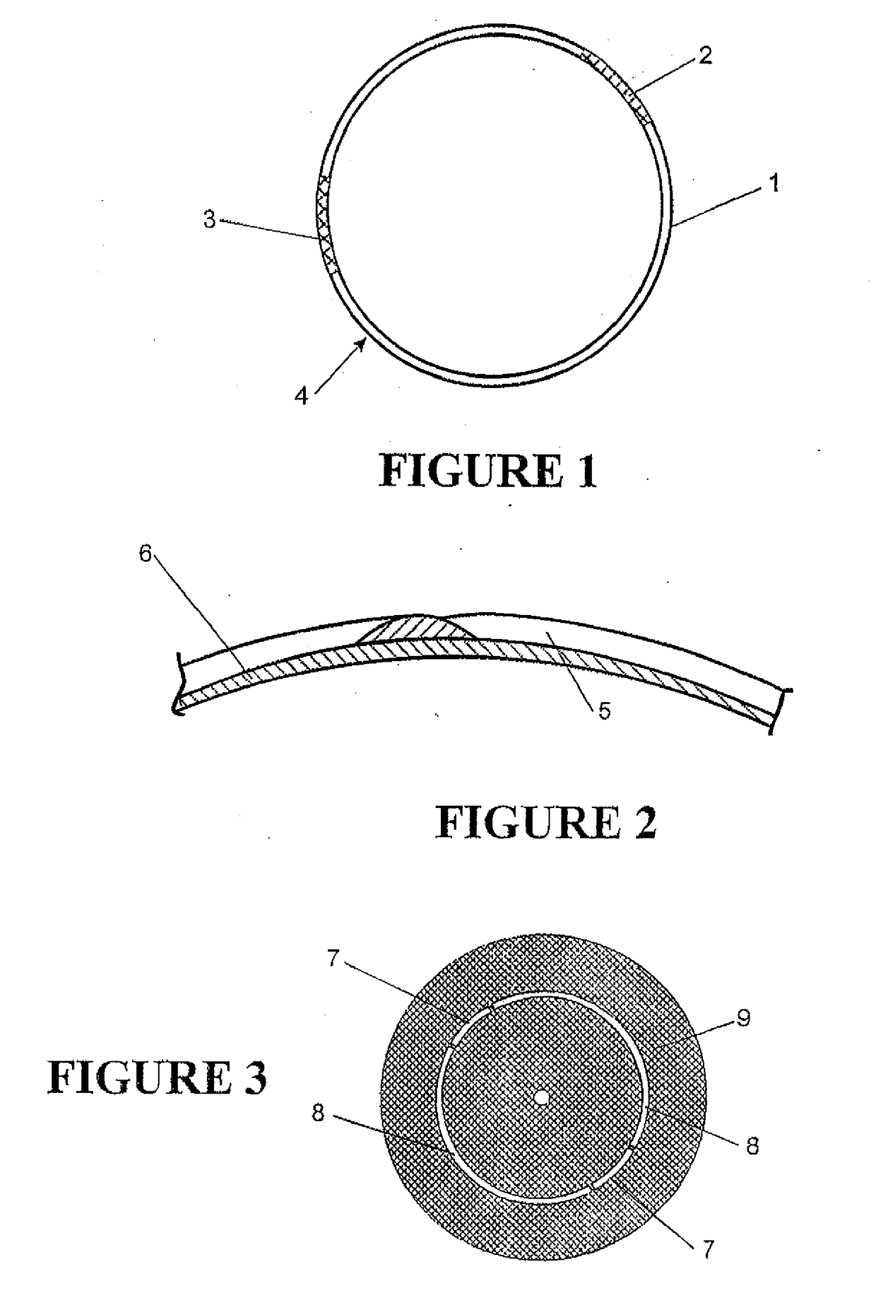
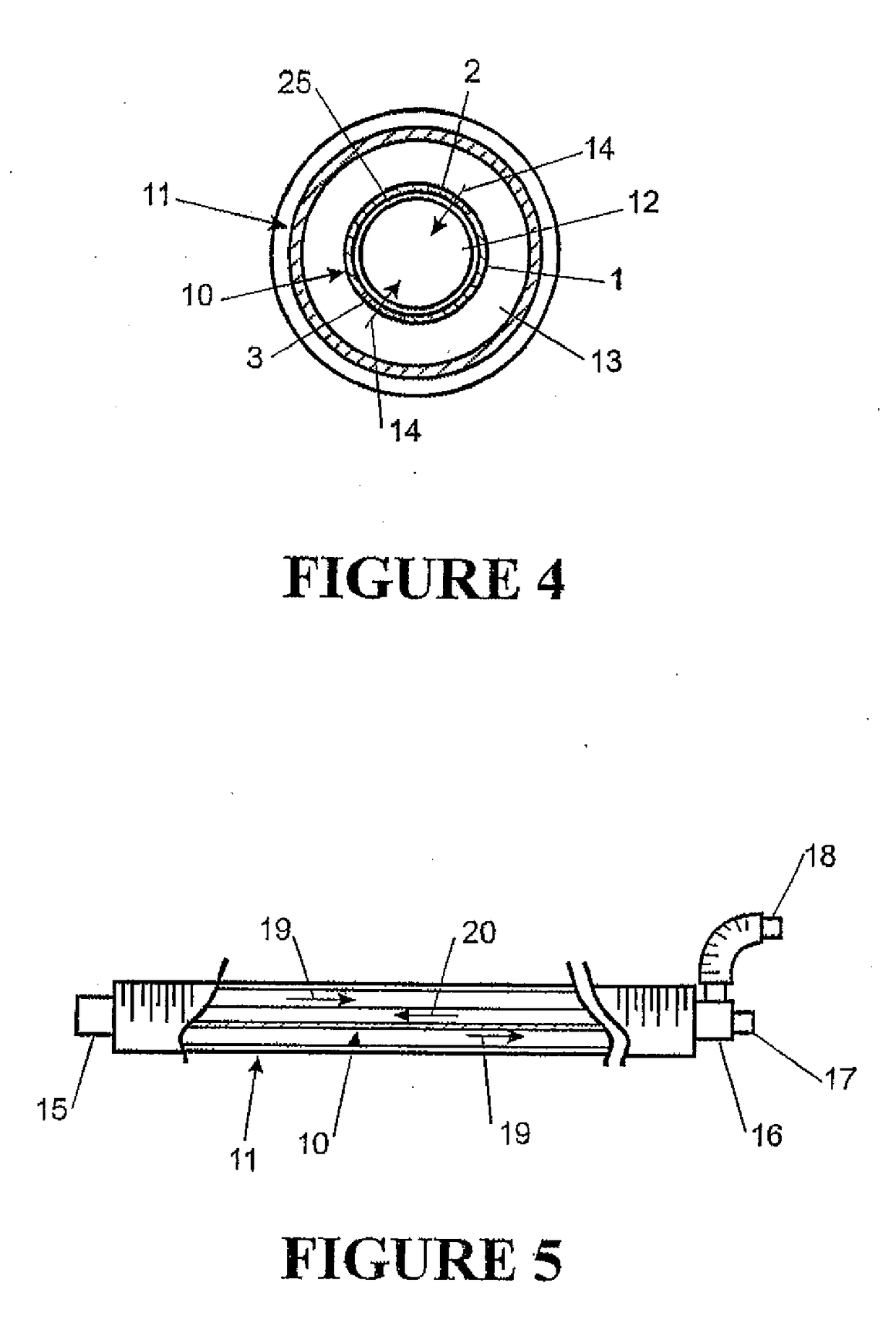
[0036]Referring to FIG. 1 in one embodiment of the invention the conduit 4 of the expiratory limb of a breathing circuit is formed having one or more longitudinal strips 2, 3 of breathable membrane as part of the wall 1 thereof.

[0037]One possible material for the breathable regions is an activated perfluorinated polymer material having extreme hydrophilic properties. An example of this polymer material is marketed under the trade mark NAFION by DuPont Fluoro products of Fayetteville USA. This material is useful due to its extreme hydrophilic properties and due to its ability to be extruded, particularly to be co-extruded in combination with other plastic materials.

[0038]Alternative materials are also envisaged including:[0039](a) Hydrophilic thermoplastics,[0040](b) woven treated fabric products exhibiting breathable characteristics

[0041]The preferred material is a hydrophilic polyester block copolymer formed into a homogeneous flat film. An example of such a film is sold under the ...


PUM

PropertyMeasurementUnit
temperatureaaaaaaaaaa
relative humidityaaaaaaaaaa

Abstract

A breathing circuit component includes an inlet, an outlet and an enclosing wall. The enclosing wall defines a gases passageway between the inlet and the outlet. At least a region of the enclosing wall is formed from a breathable material that allows the passage of water vapor without allowing the passage of liquid water or respiratory gases. The breathing circuit component may be the expiratory limb of a breathing circuit.

Description

CROSS-REFERENCE TO RELATED APPLICATIONS[0001]This application is a continuation of U.S. patent application Ser. No. 12 / 328,200, filed Dec. 4, 2008, which is a continuation of U.S. patent application Ser. No. 11 / 371,389, filed Mar. 9, 2006, now abandoned, which is a division of U.S. patent application Ser. No. 10 / 622,755, filed Jul. 18, 2003, now U.S. Pat. No. 7,140,366, issued Nov. 28, 2006, which is a division of U.S. patent application Ser. No. 09 / 850,797, filed May 8, 2001, now U.S. Pat. No. 6,769,431, issued Aug. 3, 2004, which claims the benefit of New Zealand Patent Application No. 504439, filed May 10, 2000 and New Zealand Patent Application No. 509041, filed Dec. 20, 2000, all of which are incorporated by reference in their entirety. In addition, any and all applications for which a foreign or domestic priority claim is identified in the Application Data Sheet as filed with the present application are incorporated by reference in their entirety.BACKGROUND TO THE INVENTION1. ...

Claims


Application Information

Patent Timeline
Patent Type & Authority Applications(United States)
IPC IPC(8): A61M16/08A61M16/10B29C47/00B29C53/68B29C53/58B29C47/12A61M16/04B29C48/04B29C48/07B29C48/09B29C48/30B29C53/70B29L23/00B29L31/00
CPCA61M16/0808A61M16/0883A61M16/1065B29C47/0059B29C47/122B29L2023/007B29C53/68A61M2205/7536A61M2207/10B29L2031/753B29C53/585A61M16/1045A61M2207/00B29C53/64B29C53/70A61M2230/432A61M16/08B29C48/0019B29C48/301B29C48/32B29C48/09B29C48/04B29C48/07A61M16/0875A61M16/0833A61M39/08A61M2039/082
Inventor SMITH, DANIEL JOHNMILLAR, GAVIN WALSHPOWELL, KEVIN BLAKEBALDWIN, DAVID PETER
Owner FISHER & PAYKEL HEALTHCARE LTD
Why Eureka
Try Eureka