Method for operating a turbo-machine having overload protection and turbo-machine comprising a device for carrying out said method

Active Publication Date: 2016-08-11
SIEMENS ENERGY BV
View PDF2 Cites 2 Cited by
  • Summary
  • Abstract
  • Description
  • Claims
  • Application Information

AI Technical Summary

Benefits of technology

[0019]Hitherto, directly measuring the torque at a compressor during operation was possible only with considerable effort, for example by way of strain gages attached to the rotary shaft and telemetry for transmitting the signals received from the rotating rotary shaft. As a result of the us

Problems solved by technology

Such methods are static and not very flexible.
Hitherto, directly measuring the torque at a compressor during operation was possible only with considerable

Method used


Image

  • Method for operating a turbo-machine having overload protection and turbo-machine comprising a device for carrying out said method
  • Method for operating a turbo-machine having overload protection and turbo-machine comprising a device for carrying out said method
  • Method for operating a turbo-machine having overload protection and turbo-machine comprising a device for carrying out said method

Examples


Example

Example 1

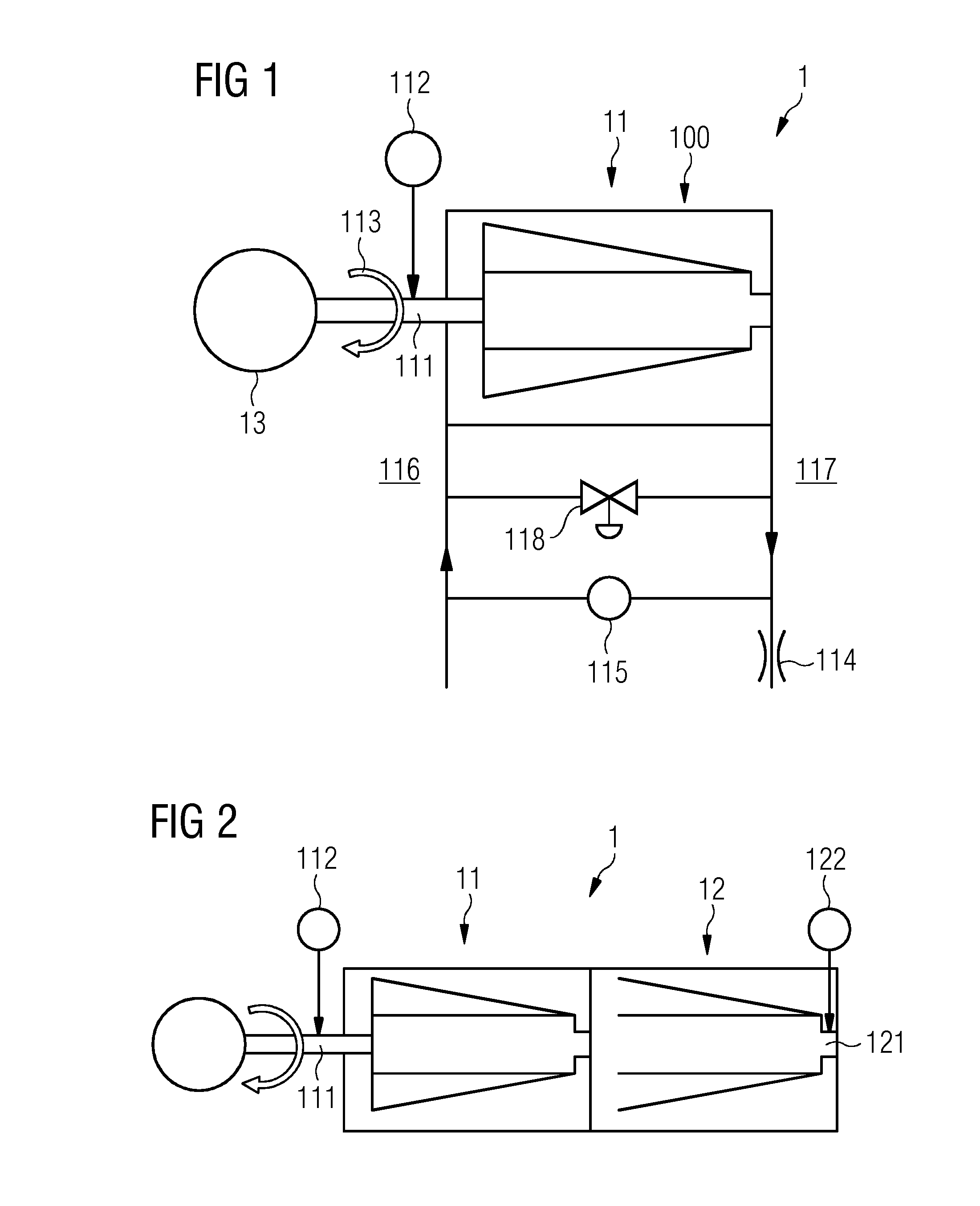
[0035]The turbocompressor 1 is an (axially or radially operated) single-shaft compressor (compressor with only one rotary shaft) having only one compressor stage (FIG. 1). The front side of the compressor stage is indicated by the reference sign 116 and the rear side of the compressor stage by 117.

Example

Example 2

[0036]In contrast to example 1, the turbocompressor 1 is a multistage single-shaft compressor (FIG. 2). The turbocompressor 1 has a turbocompressor stage 11 and at least one further turbocompressor stage 12.

[0037]The rotary shaft 111 of the compressor stage 11 and the further rotary shaft 121 of the further compressor stage 12 form a common rotary shaft.

[0038]Arranged at the further compressor stage 12 is a further magnetoelastic torque sensor 122. With the aid of the further torque sensor 122, the further torque is tapped in the region of the further rotary shaft 121.

[0039]The torque sensor 112 and the further torque sensor 122 are operated independently of one another.

Example

Example 3

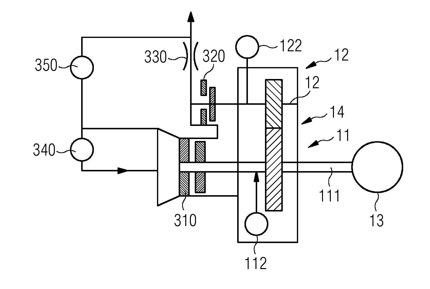
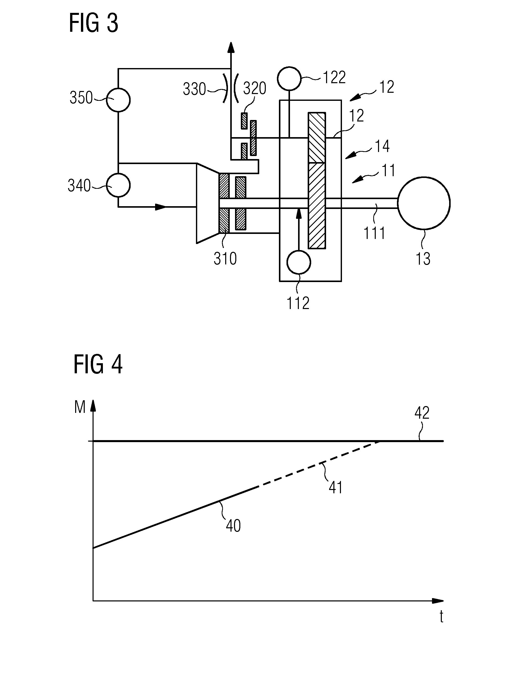
[0040]The turbocompressor 1 is a geared compressor (FIG. 3). The compressor stage 11 and the further compressor stage 12 are connected together via a gear mechanism 14. The rotary shaft 111 is driven via the motor 13. The further rotary shaft 121 is coupled to the rotary shaft 111 via the gear mechanism 14.

[0041]The torque of the rotary shaft 111 is measured via the torque sensor 112 and the further torque of the further rotary shaft 121 is measured via the further rotary torque sensor 122. The fluid to be compressed is introduced into the geared compressor and the compressed fluid is removed from the geared compressor again by the adjustable input control apparatus (ELA) 310 and the adjustable output control apparatus (ALA) 320, respectively.

[0042]Further constituent parts are a volumetric flow rate orifice plate 330 and devices for measuring the pressure differences 340 and 350 at the individual compressor stages 11 and 12.

[0043]FIG. 4 indicates how, on the basis of the m...


PUM


Abstract

A turbo-machine is provided having at least one turbo-machine stage, wherein overload protection of the rotating shaft is provided by the method and, to protect the rotating shaft against overload, a measurement of a torsional stress of the rotating shaft is carried out during operation of the rotating shaft. The torsional stress is measured via a measurement of the torque of the rotating shaft. The torque is preferably measured magneto-elastically. By using the measured torque of the rotating shaft, the development of the torque is forecast. On the basis of the forecast produced, the turbo-machine stage or operating parameters of the turbo-machine is/are regulated. Further to a turbo-machine is provided comprising at least one turbo-machine stage which has at least one rotating shaft, wherein the turbo-machine has a device for carrying out the method.

Description

CROSS-REFERENCE TO RELATED APPLICATIONS[0001]This application claims priority to PCT Application No. PCT / EP2014 / 068893, having a filing date of Sep. 5, 2014, based off of DE Application No. 10 2013 219 752.7 having a filing date of Sep. 30, 2013, the entire contents of which are hereby incorporated by reference.FIELD OF TECHNOLOGY[0002]The following relates to a method for operating a turbomachine having overload protection. The turbomachine has at least one turbomachine stage. In addition, a turbomachine having a device for carrying out the method is specified.BACKGROUND[0003]In a turbomachine, energy is transferred by a flowing fluid (gas or liquid). The energy transfer takes place in this case via a rotor with a rotary shaft (driveshaft or output shaft). Arranged on the rotary shaft are rotor blades, wings or blades which are formed such that a pressure difference (Δp) arises in the fluid flow (volumetric flow rate) between the front side and the rear side of the rotor.[0004]Curr...

Claims


Application Information

Patent Timeline
IPC IPC(8): F01D21/14G01L3/10F04D29/053F04D29/32F01D21/00F04D27/00
CPCF01D21/00F01D21/14F01D21/003G01L3/102F04D27/001F05D2220/32F05D2220/31F04D29/32F04D29/053F05D2220/40
Inventor BRUMMEL, HANS-GERDGRIESHABER, DIRKMAIER, CARL UDOPFEIFER, UWEDE BRUYN, HUUB
Owner SIEMENS ENERGY BV
Why Eureka
Try Eureka