Central valve for pivot motor actuator

Active Publication Date: 2014-10-23
HILITE GERMANY
View PDF3 Cites 20 Cited by
  • Summary
  • Abstract
  • Description
  • Claims
  • Application Information

AI Technical Summary

Benefits of technology

[0009]Thus, it is an object of the present invention to connect a quick cam adjustment with

Problems solved by technology

Timing belt adjustors, however, have to be kep

Method used


Image

  • Central valve for pivot motor actuator
  • Central valve for pivot motor actuator
  • Central valve for pivot motor actuator

Examples


Example

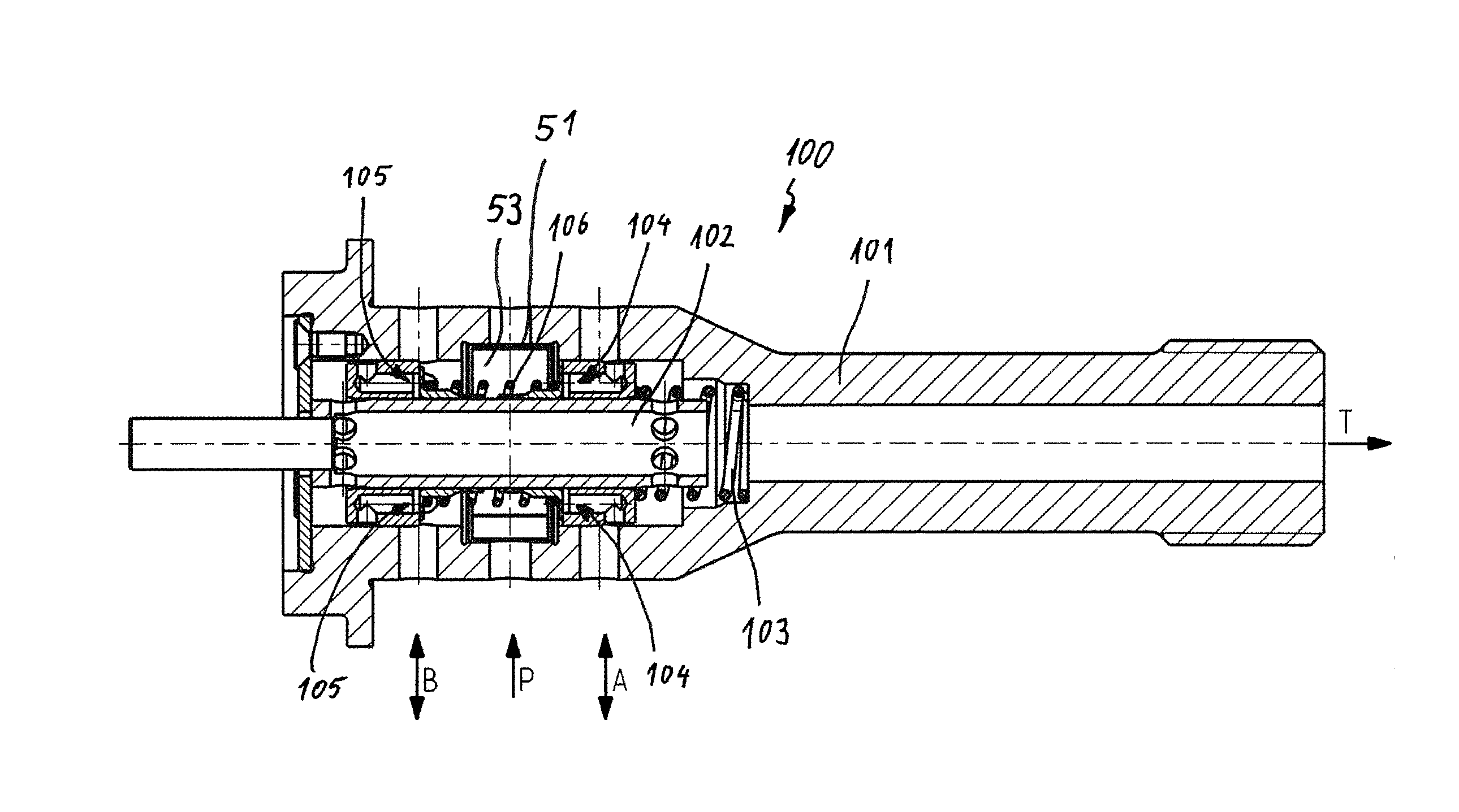
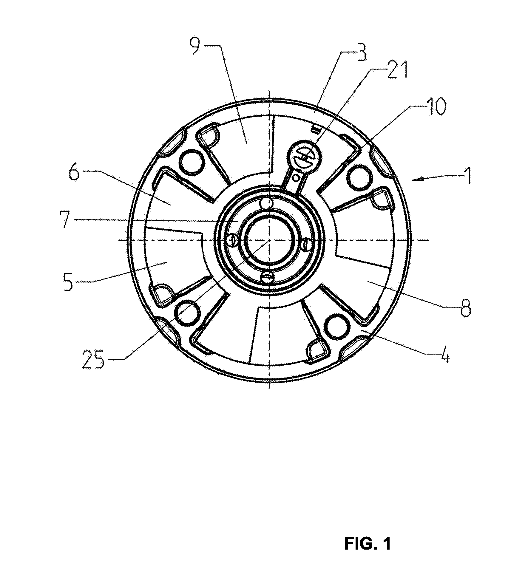
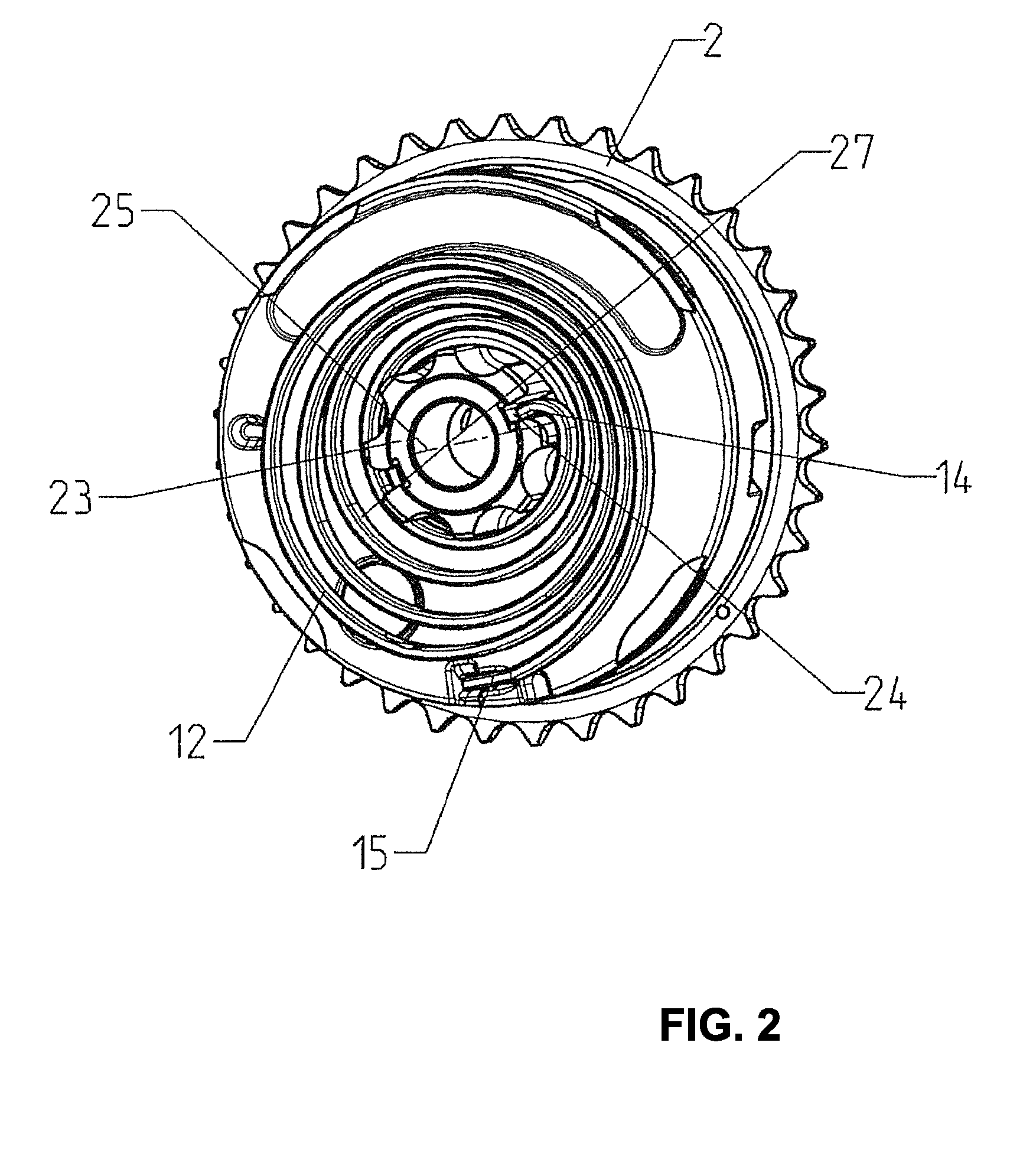
[0025]A pivot motor actuator is used to change an angular position of a cam shaft during operation of an internal combustion engine. By rotating the cam shaft opening and closing times of the gas control valves are moved so that the internal combustion engine delivers optimum power at a respective speed. The pivot motor actuator thus facilitates continuous adjustment of the cam shaft. The pivot motor actuator has a cylindrical stator 1 which is connected torque proof with a gear that is evident from FIG. 2. In the embodiment the gear 2 is a sprocket over which a chain is run that is not illustrated in detail. The gear 2, however, can also be a timing belt cog over which a drive belt is run as a drive element. The stator 1 is in a driving connection with the crank shaft through the drive element and the gear 2 in a known manner.

[0026]The stator 1 and the gear 2 can alternatively also be integrally configured in one piece when the other side of the stator 1 can be opened. Thus, the st...


PUM


Abstract

A central valve for a pivot motor actuator, the central valve including a housing tube including a first operating connection, a supply connection, a second operating connection and a tank drain connection; a piston enveloped by the housing tube and moveable relative to the housing tube, wherein the first operating connection is connected with the supply connection and the second operating connection is connected with the tank drain connection in a first position of the piston, wherein the piston is positioned in a center position in a second position, and wherein the second operating connection is connected with the supply connection and the first operating connection is connected with the tank drain connection in a third position of the piston, wherein the piston includes at least one first check valve on its outside.

Description

RELATED APPLICATIONS[0001]This application claims priority from and incorporates by reference German patent application DE 10 2013 104 051.9 filed on Apr. 22, 2013.FIELD OF THE INVENTION[0002]The invention relates to a central valve for pivot motor actuator.BACKGROUND OF THE INVENTION[0003]A central valve of this type is part of a pivot motor actuator system which includes a rotor which is adjustable through a hydraulic pressure at one of its two operating connections respectively in one of its two rotating directions.[0004]It is an ongoing development goal for pivot motor actuation systems on the one hand side to have a minimum load on a hydraulic pump since this hydraulic pump typically has to supply all consumers in a vehicle. Another development goal is quick adjustability. In order to better comply with these contradicting requirements it is known to use pressure peaks during cam shaft adjustment through check valves.[0005]In the pivot motor actuation system that is known from ...

Claims


Application Information

Patent Timeline
IPC IPC(8): F15B15/20
CPCF15B15/20F01L1/3442F01L2001/34426F01L2001/34433F01L2001/34483Y10T137/8671Y10T137/86702Y10T137/87217Y10T137/86879Y10T137/87209Y10T137/87169Y10T137/86614Y10T137/8667Y10T137/86622F16K17/105F16K11/02F16K31/0613F16K11/0716
Inventor HUTZELMANN, STEFANIEKROEPELIN, JANSCHULZE, DIETMARGOLL, JUERGEN
Owner HILITE GERMANY
Why Eureka
Try Eureka