Drilling control arrangement

Inactive Publication Date: 2007-06-19
SANDVIK TAMROCK
View PDF18 Cites 18 Cited by
  • Summary
  • Abstract
  • Description
  • Claims
  • Application Information

AI Technical Summary

Benefits of technology

[0009]A criterion to be measured, determined in a control mode, represents the effect of adjusting one or more operating parameters of drilling, this effect being measured either directly by sensors or calculated in the control unit of the rock drilling apparatus from measurement data obtained from the sensors.
[0010]The invention has the advantage that the control modes facilitate the control of drilling performed by the operator of the rock drilling apparatus. The control modes clearly describe how an individual control action affects the entire drilling situation. The operator can select the control mode optimising the target criterion that he/she considers the most important. Furthermore, the operator can switch from one control mode to another in a simple manner even during drilling as the circumstances of drilling or the control targets change.
[0011]According to an essential idea of an embodiment of the invention, the control unit comprises a user interface, where the control modes are arranged in corners of a plane geometrical polygon. The area defined by the polygon thus determines the available operating area, where the operator can move a control cursor or the like during adjustment. The

Problems solved by technology

A disadvantage of the prior art methods is that when the operator is adjusting individual operating parameters, he/she cannot perceive the effect of the adjustment measures to the entire drilling situation and the total costs of drilling.
Therefore it is very difficult to optimize drilling by adjusting individual absolute values.
Adjustment of a single drilling parameter affects p

Method used


Image

  • Drilling control arrangement
  • Drilling control arrangement
  • Drilling control arrangement

Examples


Example

[0017]For the sake of clarity, the figures show the invention in a simplified form. Like reference numerals refer to like parts.

DETAILED DESCRIPTION OF THE INVENTION

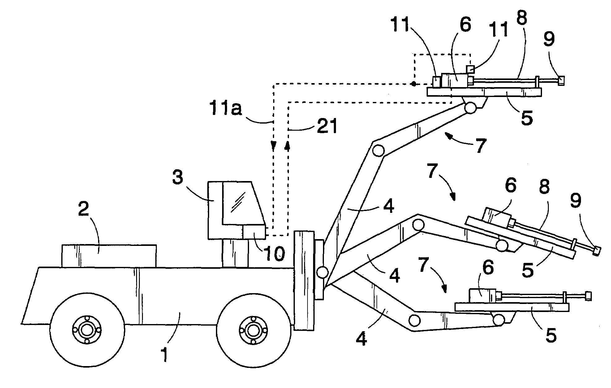
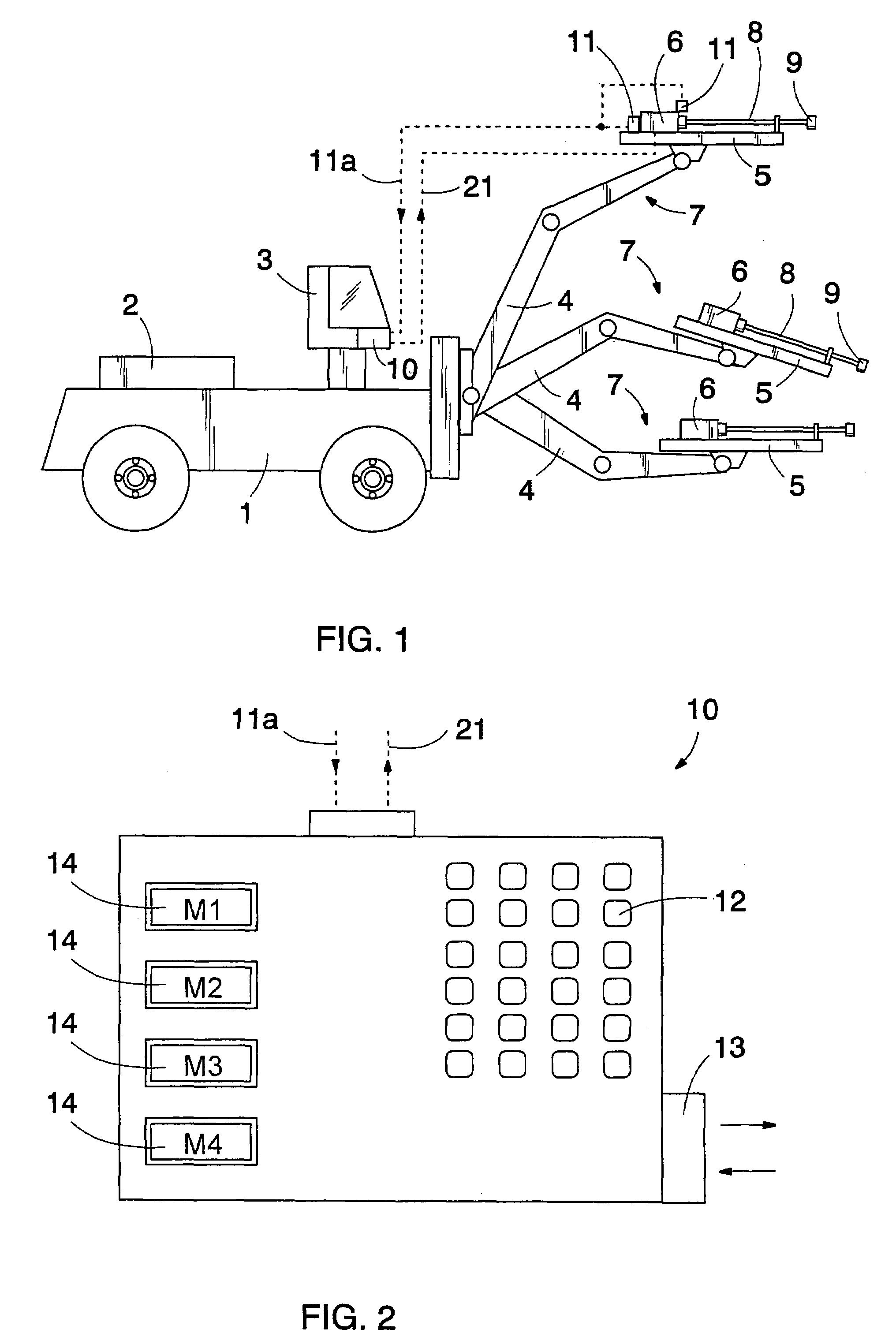
[0018]The rock drilling apparatus shown in FIG. 1 comprises a carrier 1, a power unit 2 arranged on the carrier, a control cabin 3 and in this case three drilling booms 4 that are movable with respect to the carrier. The free end of each drilling boom 4 is provided with a feeding beam 5 with a rock drill 6 arranged movably therein. The rock drill 6, the feeding beam 5 and the drilling boom 4 form a unit referred to herein as a drilling unit 7. For the sake of clarity, FIG. 1 does not show any accessory equipment required for drilling, such as devices related to replacement of drill rods 8 and a drill bit 9. The rock drilling apparatus further comprises a control unit 10 arranged on the carrier 1, preferably in the control cabin in connection with the equipment for controlling the rock drilling apparatus. The control unit...


PUM


Abstract

A method and a control system for controlling rock drilling. A control unit of a rock drilling apparatus is provided with one or more control modes, each determining the drilling variables to be measured, their threshold values and the operating principles according to which the operating parameters of drilling are controlled to achieve a desired control criterion.

Description

[0001]This application is a Continuation of International Application PCT / FI02 / 00409 filed May 14, 2002 which designated the U.S. and was published under PCT Article 21(2) in English.FIELD OF THE INVENTION[0002]The invention relates to a method of controlling rock drilling, the method comprising drilling rock with a rock drilling apparatus comprising a carrier, a feeding beam, a rock drill movable with respect to the feeding beam, and a control unit for controlling the rock drilling, the method also comprising providing a memory of the control unit with default settings for drilling, measuring the operation of the apparatus during drilling, and adjusting the operating parameters of drilling to accomplish a desired control operation. The invention further relates to a control system for a rock drilling apparatus.BACKGROUND OF THE INVENTION[0003]Rock drilling utilizes a rock drilling apparatus comprising a carrier, a feeding beam and a rock drill moved with respect to the feeding beam...

Claims


Application Information

Patent Timeline
IPC IPC(8): B25D1/00E21B44/00
CPCE21B44/00
Inventor SALMINEN, PEKKASAHA, HEIKKI
Owner SANDVIK TAMROCK
Why Eureka
Try Eureka