Fire-fighting system

Active Publication Date: 2013-07-25
HALE PRODUCTS INC
View PDF10 Cites 7 Cited by
  • Summary
  • Abstract
  • Description
  • Claims
  • Application Information

AI Technical Summary

Benefits of technology

[0006]In one aspect, a hose appliance is provided for use with a fire-fighting device. The hose appliance includes an inlet removably coupleable to a first hose and/or a first hose appliance, a first outlet removably coupleable to a second hose and/or a second hose ap

Problems solved by technology

The reliance on the engineer increases both the cost of operations and introduces the possibility of human error, as the engineer must listen to and understand verbal commands t

Method used


Image

  • Fire-fighting system
  • Fire-fighting system
  • Fire-fighting system

Examples


Example

[0014]Although specific features of various implementations may be shown in some drawings and not in others, this is for convenience only. Any feature of any drawing may be referenced and / or claimed in combination with any feature of any other drawing.

DETAILED DESCRIPTION

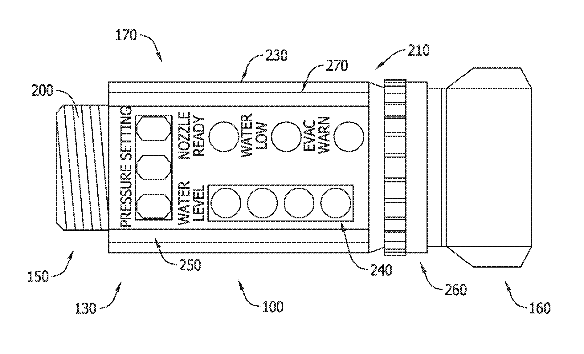
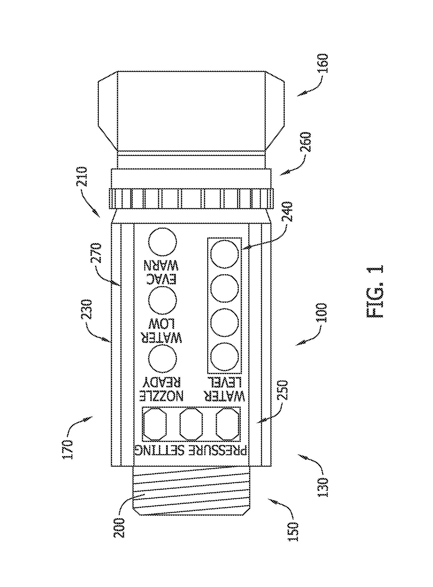
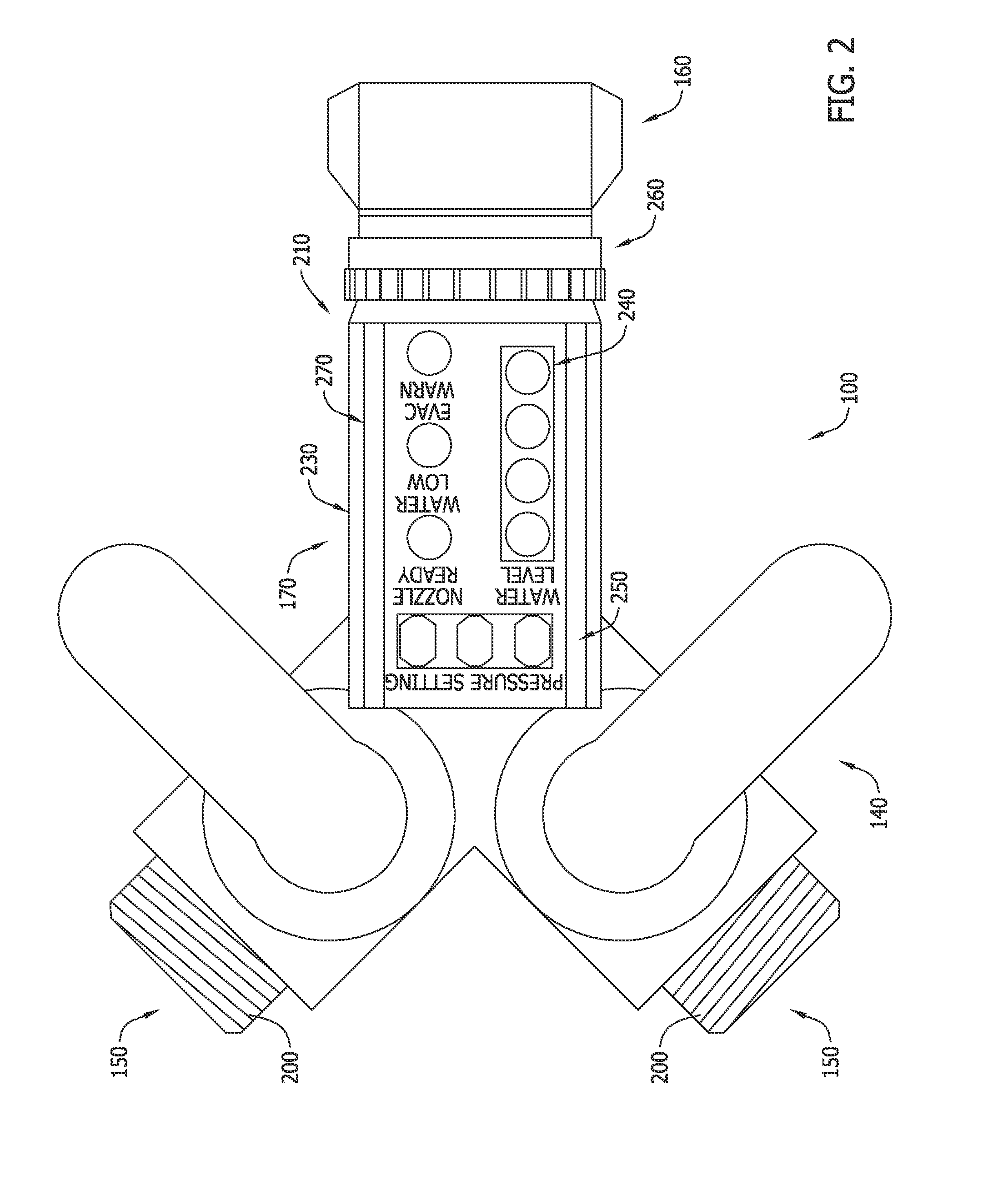
[0015]The present disclosure relates to fire-fighting systems, and more specifically, to methods and systems for use in controlling fluid flow. In one embodiment, a hose appliance includes an inlet that is removably coupleable to a first hose and / or a first hose appliance, an outlet that is removably coupleable to a second hose and / or to a second hose appliance, a body that extends between the inlet and the outlet, and a control module that includes a transceiver that receives data from the fire-fighting device and that transmits data to the fire-fighting device to facilitate controlling the fire-fighting device.

[0016]As used herein, an element or step recited in the singular and preceded with the word “a” or “an” s...


PUM


Abstract

A hose appliance is provided for use with a fire-fighting device. The hose appliance includes an inlet removably coupleable to a first hose and/or a first hose appliance, a first outlet removably coupleable to a second hose and/or a second hose appliance, a body extending between the inlet and the first outlet, and a control module including a transceiver configured to receive data from the fire-fighting device and to transmit data to the fire-fighting device to facilitate controlling the fire-fighting device.

Description

CROSS-REFERENCE TO RELATED APPLICATIONS[0001]This application claims the benefit of U.S. Provisional Patent application Ser. No. 61 / 588,452, filed Jan. 19, 2012, which is herein incorporated by reference in its entirety.BACKGROUND[0002]The field of the disclosure relates generally to fire-fighting systems, and more specifically, to methods and systems for use in controlling fluid flow.[0003]Fire-fighting devices (e.g., pumper trucks) are used to fight fires by pumping fluid (e.g., water, foam, or another flame retardant) from a source through hose lines wherein the liquid may be directed, i.e., sprayed, on a fire to facilitate the extinguishing or containing the fire. Known pumper trucks include controls to regulate the operation of the truck and to control the flow of liquid from the truck into the hose lines. Such controls generally include a plurality of valves used to control the flow of liquid to a fire pump from a storage tank transported onboard the truck or from another liqu...

Claims


Application Information

Patent Timeline
IPC IPC(8): A62C37/00
CPCA62C33/00A62C37/00B60K7/0007B60K2007/0038B60K2007/0092B62K1/00H02K7/003H02K7/006H02K7/14H02K9/223H02K9/227B60L50/64B62K11/007H02K1/187H02K15/02Y02T10/64Y02T10/70Y02T90/16A62C31/02A62C27/00B07C3/12B62K11/02B62K2202/00B62M7/12H02K5/02B60L50/50H02K9/22G05B15/02G05D7/0635
Inventor CERRANO, JASON
Owner HALE PRODUCTS INC
Why Eureka
Try Eureka