Windshield washer valve

Inactive Publication Date: 2000-12-05
MANNESMANN VDO AG
View PDF15 Cites 19 Cited by
  • Summary
  • Abstract
  • Description
  • Claims
  • Application Information

AI Technical Summary

Benefits of technology

is to improve a valve device of the above-mentioned type primarily with respect to flow te

Problems solved by technology

Despite the relatively simple external construction, this arrangement has certain disadvantages with regard to flow through the nonreturn valve.
On leaving the f

Method used


Image

  • Windshield washer valve
  • Windshield washer valve

Examples


Embodiment Construction

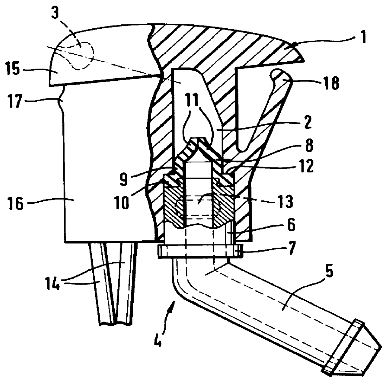
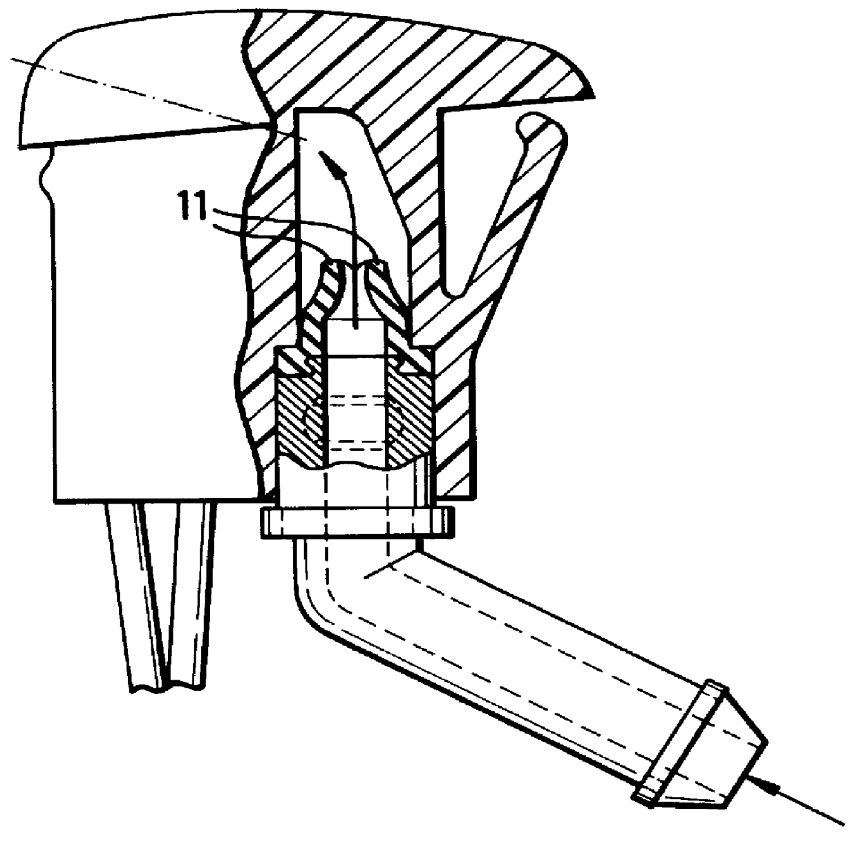
According to FIG. 1, a housing 1, which is preferably made of moldable plastic, has a duct 2 hollowed out in it. A dash-dotted line which points obliquely upward to the left shows the continuation of the duct to a nozzle 3 (indicated in a dot-dashed line). A tubular connecting piece 4 is inserted into that end of the duct 2 which is remote from the nozzle 3.

The connecting piece 4 essentially comprises a flexible tube stub 5 which protrudes outward out of the housing 1, extends here at an angle with respect to the duct 2 and has an end-side thickened portion, which makes it difficult to pull off a flexible tube which has been pulled on (not shown here) the outside of the flexible tube stub 5, and a cylindrical insertion section 6 which is introduced into the duct 2 and has an end which is open toward the duct 2. At a distance from the duct-side end of the insertion section, an annular collar 7 protrudes over the outer circumferential surface of the connecting piece, the external diam...


PUM


Abstract

A valve device, in particular a window and lens cleaning device in motor vehicles, includes a housing (1) with a duct (2) and at least one nozzle (3), and also a tubular connecting piece (4) for feeding a pressurized fluid, in particular a cleaning liquid, into the duct and to the nozzle. The connecting piece (4) is provided at its nozzle-side end with a nonreturn valve which blocks a return flow from the nozzle to the connecting piece, wherein the connecting piece (4) is open at its nozzle-side end. The nonreturn valve comprises of an elastic shaped part (8) with a mouth which is normally closed and can be opened by the pressure of the cleaning liquid.

Description

FIELD AND BACKGROUND OF THE INVENTIONThe invention relates to a valve device, in particular a window and lens cleaning device in motor vehicles.There is a device which essentially comprises a plastic nozzle housing with a duct, two nozzles inserted at its end and also a connecting piece which is inserted into the duct on the other side and is fastened therein in a sealed manner, for feeding a cleaning liquid to the nozzles. At its end which faces the nozzles, the tubular connecting piece is provided with a nonreturn valve. This prevents the cleaning liquid from flowing back if the delivery pressure is reduced, for example by the relevant pump being switched off.In detail, the known nonreturn valve is of similar construction to the inner tube valves known from older bicycle inner tubes. On its nozzle-side end, the tubular connecting piece is closed but has at least one hole in its circumferential surface. This hole is covered by a thin and elastic flexible tube which is pulled over t...

Claims


Application Information

Patent Timeline
IPC IPC(8): B60S1/46B60S1/52F16K15/14
CPCF16K15/147B60S1/52Y10T137/7882
Inventor MARTIN, UWE
Owner MANNESMANN VDO AG
Why Eureka
Try Eureka