Method of connecting terminal and electric wire

a technology of connecting terminals and electric wires, which is applied in the direction of electric connection bases, connection contact material, and connection formation by deformation, etc., can solve the problems of troublesome operation, leakage of sealing material b>58/b> injected from the opening of large diameter pipes b>51/b>, and achieves satisfactory electrical conductivity. , the effect of lightening the weigh

Active Publication Date: 2007-02-13
YAZAKI CORP
View PDF7 Cites 79 Cited by
  • Summary
  • Abstract
  • Description
  • Claims
  • Application Information

AI Technical Summary

Benefits of technology

[0018]In view of the above mentioned circumstances, accordingly it is an object of the invention to provide a method of connecting a terminal and an electric wire, being capable of waterproofing the wire connection part with less member of parts and at low cost, and effecting stable electrical conductivity.
[0025]According to the above structure, the conductive adhesive goes into spaces in a side of the electric contact part or spaces in the electric wire by pressure effected when tightening the tubular wall. If the conductive adhesive goes into the space in the side of the electric contact part, the space is closed by the conductive adhesive, and a water is prevented from invading into the wire connection part from an exterior. If the conductive adhesive goes into between wires, the contact resistance is low between the mutual wires, and the electrical conductivity is heightened.
[0027]According to the above structure, a plurality of dice arranged radially in the rotary swaging apparatus are moved to a radial direction in cooperation with backers (hammers), so that the terminal is struck at the tubular wall periodically and the tubular wall is tightened evenly all over the circumference, and the terminal and the electric wire are closely adhered. Therefore, no space is formed between the terminal and the electric wire to more heighten the waterproofing property as well as heighten the electrical conductivity between the terminal and the electric wire.
[0029]According to the above structure, since an epoxy resin as the binder is thermosetting, a curing time is short to heighten the connection workability of the terminal and the electric wire, and being irreversible, if being once hardened, the waterproofing property is maintained for a long period of time. Since the nickel power is conductive, the electrical conductivity between the core wire portion and the wire connection part is satisfactory.
[0031]According to the above structure, since the nickel paste and the aluminum alloy contact at low contact resistance, a satisfactory electrical conductivity may be available. In addition, when the tubular wall of the wire connection part is tightened, since the nickel powder as a conductive filler of the nickel paste breaks through an amorphous oxidized film of the aluminum alloy and the nickel powder directly contacts an underground layer of the aluminum alloy, the terminal and the electric wire can be connected without performing a pretreatment for removing the oxidized film. Further, if using an aluminum electric wire, a vehicle such as an automobile is lightened in weight comparing with using a copper electric wire.

Problems solved by technology

However, the above mentioned prior methods of connecting the terminal and the electric wire are involved with problems to be solved, as follows.
As the connection between the large diameter pipe 51 and the small diameter pipe 52 is conducted by press fitting or welding, there arises a problem that the operation is troublesome.
Besides, it is possible that the connection portion does not have sufficient sealing condition due to welding defects, or pressure shortage during connecting operation by press fitting.
In such the case, there is a fear that the sealing material 58 injected from the opening of the large diameter pipe 51 could leak out.
The second related art heats the shrinkage tube 63 to a predetermined temperature to reduce the size thereof in order to cover the wire connection part 62 of the terminal 60 for attaining the waterproof and an insulation, but since rate of shrinkage is decided depending on sizes or material qualities, those should be used properly, and a problem is present in a connection workability being inferior.
), and the waterproofing property of the heat shrinkage tube 63 might be spoiled.
As a result, the connection portion could be abnormally heated more easily, thereby causing a melting of the hot melt adhesive.

Method used


Image

  • Method of connecting terminal and electric wire
  • Method of connecting terminal and electric wire
  • Method of connecting terminal and electric wire

Examples


Embodiment Construction

[0038]Explanation will be made in detail to embodied examples of the invention, referring to the attached drawings.

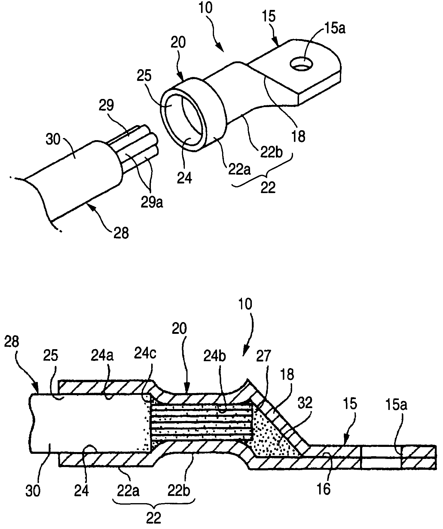
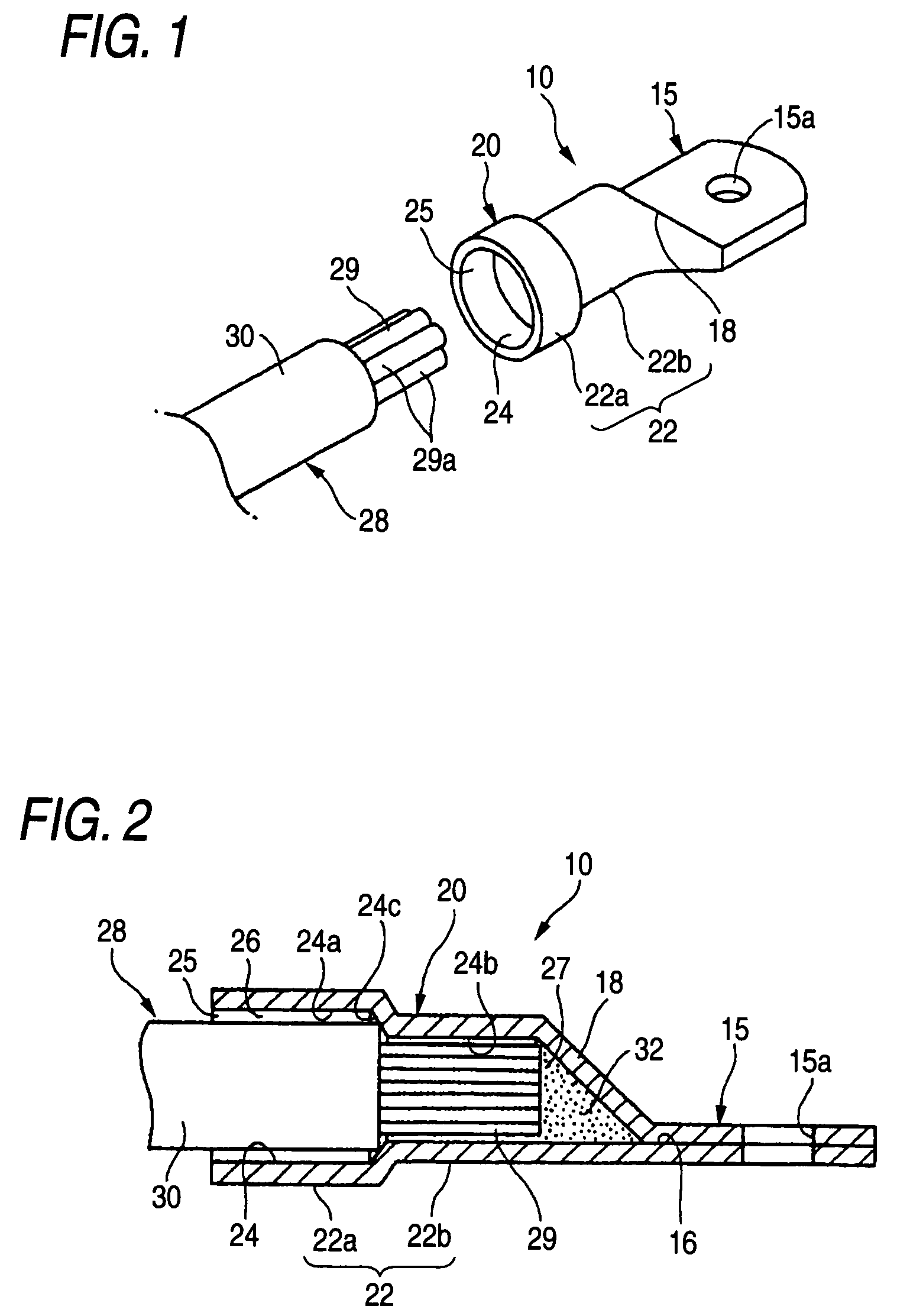
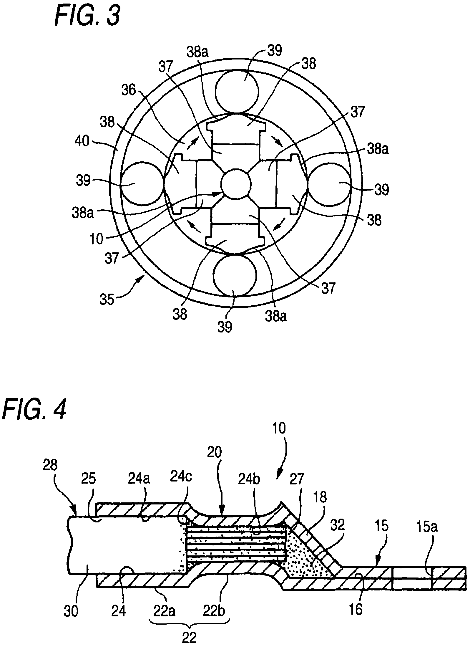
[0039]FIGS. 1 to 4 show one embodiment of the connecting method of the terminal and the electric wire.

[0040]FIG. 1 shows an earth terminal (terminal) of the aluminum alloy as a composing material and an aluminum electric wire (electric wire) 28 to be connected to the earth terminal. An earth current flows in the aluminum electric wire 28 and to a car panel or an engine block (both not shown) through the earth terminal 10.

[0041]The aluminum electric wire 28 is made of a core wire portion 29 composed of plural wires 29a and an insulation covering portion 30 covering the circumference of the core wire portion 29. In the present embodiment, the core wire portion 29 is composed of the aluminum alloy, but the invention does not limit to the aluminum alloy, but may employ aluminum, copper or Cu alloy. Using Al or aluminum alloy in substitution for Cu or Cu alloy, specific grav...


PUM

PropertyMeasurementUnit
softening temperatureaaaaaaaaaa
temperatureaaaaaaaaaa

Abstract

The invention comprises filling a conductive adhesive on a hole end of a wire connection part in tubular shape of the terminal which has an electric contact part at one side and the wire connection part at the other side, inserting an electric wire from a hole opening of the wire connection part toward the hole end, and reducing evenly a size of a tubular wall of the wire connection part, thereby causing the conductive adhesive to infiltrate into a space of the electric contact part or between wires. The invention also comprises tightening the tubular wall of the wire connection part by a rotary swaging process. Further, the conductive adhesive is a nickel paste which is a mixture of nickel powders in a liquid epoxy resin based binder. In addition, at least one of a core wire portion of the electric wire or the terminal is aluminum or aluminum alloy.

Description

[0001]The present application is based on Japanese Patent Application No. 2002-369388, the entire contents of which are incorporated herein by reference.BACKGROUND OF THE INVENTION[0002]1. Field of the Invention[0003]The invention relates to a method of connecting a terminal and an electric wire, which connects the terminal to be connected to, for example, a car panel or an engine block and the an electric wire supplying an earth current.[0004]2. Related Art[0005]As one of examples of a related art concerned with this kind of connecting method of the terminal and the electric wire, known are those shown in FIGS. 5 and 6 (See Japanese Patent Publications Nos. JP H11-86921A and JP 2000-285983A.).[0006]As shown in FIG. 5, a first related art (Japanese Patent Publication No. JPH11-86921A, pp. 2 to 4 & FIG. 7) lessens invasion of a sealing material 58 into a wire connection part between a core wire portion 57a and the terminal 50 for realizing stable electrical connection, and closing an...

Claims


Application Information

Patent Timeline
Patent Type & Authority Patents(United States)
IPC IPC(8): H01R43/00H05K13/00H01R4/04H01R11/12H01R11/28
CPCH01R4/04H01R4/62H01R11/12H01R11/28Y10T29/49151Y10T29/49139Y10T29/49174Y10T29/49181Y10T29/49178Y10T29/49169Y10T29/49194
Inventor ONUMA, MASANORI
Owner YAZAKI CORP
Why Eureka
Try Eureka